

Question: For the programmable logic block shown in Figure 5-13, show the necessary configuration settings to implement each of the following types of circuits. You can
For the programmable logic block shown in Figure 5-13, show the necessary configuration settings to implement each of the following types of circuits. You can assume that the upper data input of each multiplexer is chosen with a select input of 0.
(a) A combinational function of inputs a, b, and c.
(b) A Moore machine
(c) A Mealy machine
Figure 5-13
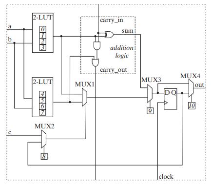
b 2-LUT 1 2 2-LUT MUX2 18 MUXI carry_in sum addition logic carry out MUX3 DQ clock www MUX4 out 10
Step by Step Solution
3.31 Rating (157 Votes )
There are 3 Steps involved in it
Heres how we can configure the block for each scenario a Combinational Function of Inputs a b and c ... View full answer

Get step-by-step solutions from verified subject matter experts