

Question: Implement the state machine diagram in Figure 6-38 by using one lip-lop per state assignment. Figure 6-38 Default: Z=0 W N (STA) W RESET (STB)
Implement the state machine diagram in Figure 6-38 by using one lip-lop per state assignment.
Figure 6-38
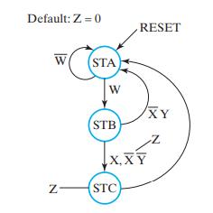
Default: Z=0 W N (STA) W RESET (STB) X,XY (STC) XY
Step by Step Solution
★★★★★
3.39 Rating (158 Votes )
There are 3 Steps involved in it
1 Expert Approved Answer
Step: 1 Unlock

Present state A B C 1 STA 0 1 0 0 Input Next state Output DA AWBXYC A B C ... View full answer
Question Has Been Solved by an Expert!
Get step-by-step solutions from verified subject matter experts
Step: 2 Unlock
Step: 3 Unlock