

The outputs of registers R0, R1, R2, and R3 are connected through 4-to-1 multiplexers to the inputs
Question:
The outputs of registers R0, R1, R2, and R3 are connected through 4-to-1 multiplexers to the inputs of a ifth register, R4. Each register is 8 bits long. The required transfers, as dictated by four control variables, are
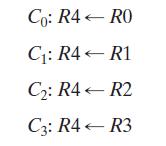
The control variables are mutually exclusive (i.e., only one variable can be equal to 1 at any time) while the other three are equal to 0. Also, no transfer into R4 is to occur for all control variables equal to 0.
(a) Using registers and a multiplexer, draw a detailed logic diagram of the hardware that implements a single bit of these register transfers.
(b) Draw a logic diagram of the simple logic that maps the control variables as inputs to three outputs: the two select variables for the multiplexer and the load signal for the register R4.
Step by Step Answer:
RO R1 0723 O MUX S So R2 ...View the full answer


Logic And Computer Design Fundamentals
ISBN: 9780133760637
5th Edition
Authors: M. Morris Mano, Charles Kime, Tom Martin
