

Question: Repeat Problem 6-26 using one multiplexer-based bus and one direct connection from one register to another instead of dedicated multiplexers. Problem 6-26 Logic to implement
Repeat Problem 6-26 using one multiplexer-based bus and one direct connection from one register to another instead of dedicated multiplexers.
Problem 6-26
Logic to implement transfers among three registers, R0, R1, and R2, is to be implemented. Use the control variable assumptions given in Problem 6–20. The register transfers are as follows:
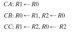
Using registers and dedicated multiplexers, draw a detailed logic diagram of the hardware that implements a single bit of these register transfers.
Draw a logic diagram of simple logic that converts the control variables CA, CB, and CC as inputs to outputs that are the SELECT inputs for the multiplexers and LOAD signals for the registers.
Problem 6–20
The outputs of registers R0, R1, R2, and R3 are connected through 4-to-1 multiplexers to the inputs of a ifth register, R4. Each register is 8 bits long. The required transfers, as dictated by four control variables, are
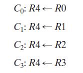
The control variables are mutually exclusive (i.e., only one variable can be equal to 1 at any time) while the other three are equal to 0. Also, no transfer into R4 is to occur for all control variables equal to 0.
(a) Using registers and a multiplexer, draw a detailed logic diagram of the hardware that implements a single bit of these register transfers.
(b) Draw a logic diagram of the simple logic that maps the control variables as inputs to three outputs: the two select variables for the multiplexer and the load signal for the register R4.
CA: R1 < CB: R0 CC: R1 R0 R1, R2 - RO R2, R0 - R2 RO-
Step by Step Solution
3.43 Rating (159 Votes )
There are 3 Steps involved in it
Heres how we can proceed a Detailed Logic Diagram We will use one multiplexerbased bus to facilitate ... View full answer

Get step-by-step solutions from verified subject matter experts