

Two register transfer statements are given (otherwise, R1 is unchanged): (a) Using a 4-bit counter with parallel
Question:
Two register transfer statements are given (otherwise, R1 is unchanged):
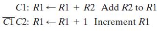
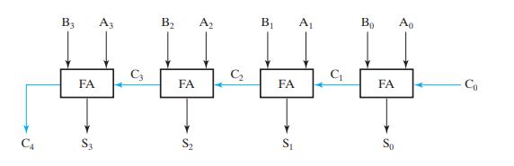
(a) Using a 4-bit counter with parallel load as in Figure 6-14 and a 4-bit adder as in Figure 4-5, draw the logic diagram that implements these register transfers.
(b) Repeat part (a) using a 4-bit adder as in Figure 3-43 plus external gates as needed. Compare with the implementation in part (a).
Figure 4-5
Figure 6-14
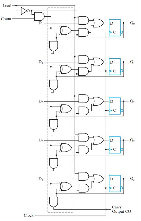
Figure 3-43
Fantastic news! We've Found the answer you've been seeking!
Step by Step Answer:
a CLK b Clock R2 REG 4 D03 03 C1 ...View the full answer

Answered By
Somy Singh
I have done post graduation in chemistry from IIT Bhubaneswar keen to teach students for various competitive exams and academics. I will do my level best to teach students with best of my knowledge.
0 Reviews
10+ Question Solved
Related Book For 

Logic And Computer Design Fundamentals
ISBN: 9780133760637
5th Edition
Authors: M. Morris Mano, Charles Kime, Tom Martin
Question Posted:
