

Question: Using Figure 3-51 as a guide and a binary decision on S from Figure 3-34, write a high-level behavior Verilog description for the addersubtractor in
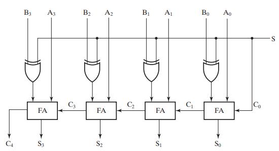
Using Figure 3-51 as a guide and a “binary decision” on S from Figure 3-34, write a high-level behavior Verilog description for the adder–subtractor in Figure 3-46 (see Figure 3-45 for details). Compile and simulate your description. Assuming a ripple carry implementation, apply input combinations to your design that will (1) cause all 16 possible input combinations to be applied to the full adder–subtractor stage for bit 2, and (2) simultaneously cause the carry output of bit 2 to appear at one of your design’s outputs. Also, apply combinations that check the carry chain connections between all full adders by demonstrating that a 0 and a 1 can be propagated from C0 to C4.
Figure 3-51
![// 4-bit Adder: Behavioral Verilog Description module adder_4_b_v (A, B, CO, S, C4); input [3:0] A, B; input](https://dsd5zvtm8ll6.cloudfront.net/images/question_images/1704/4/5/9/0846597fb4ce3c741704459084682.jpg)
Figure 3-34
Figure 3-36
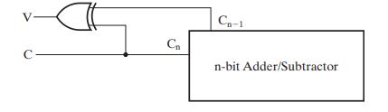
Figure 3-45
// 4-bit Adder: Behavioral Verilog Description module adder_4_b_v (A, B, CO, S, C4); input [3:0] A, B; input C0; output [3:0] S; output C4; assign (C4, S} = A + B + CO; endmodule
Step by Step Solution
3.45 Rating (161 Votes )
There are 3 Steps involved in it

Get step-by-step solutions from verified subject matter experts