

Question: Perform a manual or computer- based logic simulation similar to that given in Figure 4-5 for the SR latch with control input C in Figure
Perform a manual or computer- based logic simulation similar to that given in Figure 4-5 for the SR latch with control input C in Figure 4-7. In particular, examine the behavior of the circuit when S and R are changed while C has the value 1.
Figure 4-5
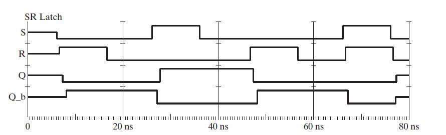
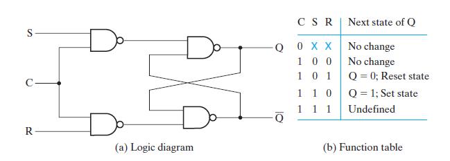
Figure 4-7
SR Latch S R Q_b ........................ 40 ns 0 20 ns 60 ns 80 ns
Step by Step Solution
★★★★★
3.37 Rating (163 Votes )
There are 3 Steps involved in it
1 Expert Approved Answer
Step: 1 Unlock

The images provided show an SR latch timing diagram and the logic diagram along with the function ta... View full answer
Question Has Been Solved by an Expert!
Get step-by-step solutions from verified subject matter experts
Step: 2 Unlock
Step: 3 Unlock