

Question: Using Figure 3-49 as a guide and a when-else on S from Figure 3-29, write a high-level behavior VHDL description for the addersubtractor in Figure
Using Figure 3-49 as a guide and a “when-else” on S from Figure 3-29, write a high-level behavior VHDL description for the adder–subtractor in Figure 3-46 (see Figure 3-45 for details). Compile and simulate your description.
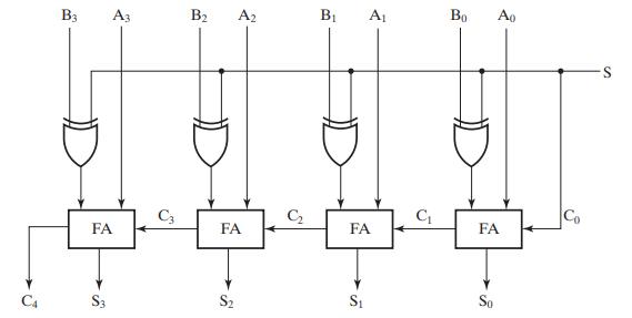
Assuming a ripple carry implementation, apply combinations that check out one of the full adder–subtractor stages for all 16 possible input combinations. Also, apply combinations to check the carry chain connections in between the full adders by demonstrating that a 0 and a 1 can be propagated from C0 to C4. Check the overflow signals as well.
Figure 3-49
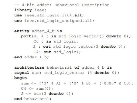
Figure 3-46
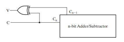 Figure 3-45
--4-bit Adder: Behavioral Description library ieee; use use ieee.std_logic_1164.all; ieee.std_logic_unsigned.all; entity adder_4_b is. port (B, A in std_logic_vector (3 downto 0); CO in std_logic; S out std_logic_vector (3 downto 0); C4: out std_logic); end adder_4_b; architecture behavioral of adder_4_b is signal sum: std_logic_vector (4 downto 0); begin sum
Step by Step Solution
3.37 Rating (147 Votes )
There are 3 Steps involved in it
The question appears to ask for a VHDL VHSIC Hardware Description Language code snippet that impleme... View full answer

Get step-by-step solutions from verified subject matter experts