

Question: For the mechanism shown in Fig.3.18(a), find the angular accelerations of the links (A B, B O_{2}) and the linear accelerations of points (C, D),
For the mechanism shown in Fig.3.18(a), find the angular accelerations of the links \(A B, B O_{2}\) and the linear accelerations of points \(C, D\), and E. \(\omega=10 \mathrm{rad} / \mathrm{s}, \alpha=200 \mathrm{rad} / \mathrm{s}^{2}\).
\[ \begin{gathered} O_{1} \mathrm{O}_{2}=100 \mathrm{~mm}, O_{1} A=50 \mathrm{~mm}, A B=45 \mathrm{~mm}, A D=30 \mathrm{~mm}, A C=45 \mathrm{~mm} \\ B C=30 \mathrm{~mm}, O_{2} B=55 \mathrm{~mm}, O_{2} E=45 \mathrm{~mm}, \text { and } B E=25 \mathrm{~mm} \end{gathered} \]
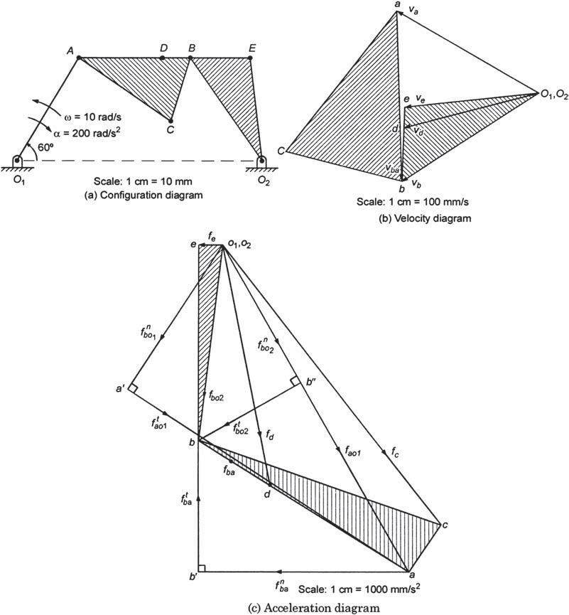
60 = 10 rad/s a = 200 rad/s D B E 0 Scale: 1 cm = 10 mm 02 (a) Configuration diagram fb01 01.02 fot fb02 fb02 D for fba b' fd b" 5 bvb Scale: 1 cm = 100 mm/s (b) Velocity diagram fao1 fba Scale: 1 cm = 1000 mm/s (c) Acceleration diagram 1,02
Step by Step Solution
There are 3 Steps involved in it
Velocity diagram 1 Draw the configuration diagram shown in Fig318 a to a scale of 1 mathrmcm10 mathrmmm 2 Given omega10 mathrmrad mathrms vaomega time... View full answer

Get step-by-step solutions from verified subject matter experts