

Question: The chart for exploring stiff composites with light alloy or polymer matrices is shown below. A construction like that of Fig. 12.11 of the text
The chart for exploring stiff composites with light alloy or polymer matrices is shown below. A construction like that of Fig. 12.11 of the text allows the potential of any given matrix-reinforcement combination to be assessed. Four matrix materials are shown, highlighted in red. The materials shown in green are available as fibres (f), whiskers (w) or particles (p). The criteria of excellence (the indices \(E / ho, E^{1 / 2} / ho\) and \(E^{1 / 3} / ho\) for light, stiff structures) are shown; they increase in value towards the top left. Use the chart to compare the performance of a titaniummatrix composite reinforced with
(a) zirconium carbide, \(\mathrm{ZrC}\),
(b) Saffil alumina fibres
(c) Nicalon silicon carbide fibres. Keep it simple to calculate the density and upper and lower bounds for the modulus at a volume fraction of \(f=0.5\) and plot these points. Then sketch arcs of circles from the matrix to the reinforcement to pass through them. In making your judgement, assume that \(f=0.5\) is the maximum practical reinforcement level.
Data From Fig, 12.11
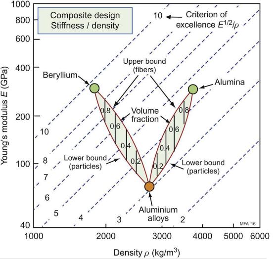
Young's modulus E (GPa) 1000 800 Composite design Stiffness / density 10 600 400 Beryllium Upper bound (fibers) Volume 200 fraction 06 10 06 04 8 Lower bound 100 (particles) 7 -- 40 1000 6 5 Criterion of excellence E1/2/p Lower bound (particles) Alumina Aluminium 3 alloys 2 MFA 16 2000 3000 4000 5000 6000 Density p (kg/m)
Step by Step Solution
3.45 Rating (148 Votes )
There are 3 Steps involved in it

Get step-by-step solutions from verified subject matter experts