

Question: Draw the waveform for the output Q in the JK circuit of Figure A.31, using the input waveforms shown in Figure PA.4 and assuming that
Draw the waveform for the output Q in the JK circuit of Figure A.31, using the input waveforms shown in Figure PA.4 and assuming that the flip-flop is initially in the O state.LO1 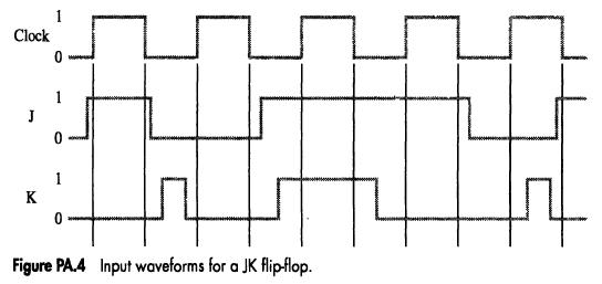
1 Clock 0 1 J 1 K 0 Figure PA.4 Input waveforms for a JK flip-flop.
Step by Step Solution
★★★★★
3.40 Rating (147 Votes )
There are 3 Steps involved in it
1 Expert Approved Answer
Step: 1 Unlock

Question Has Been Solved by an Expert!
Get step-by-step solutions from verified subject matter experts
Step: 2 Unlock
Step: 3 Unlock