

Question: Solid oxide fuel cells (SOFC) have been proposed as an alternative energy technology for use in large stationary power applications (1 to 10MWof electrical power).
Solid oxide fuel cells (SOFC) have been proposed as an alternative energy technology for use in large stationary power applications (1 to 10MWof electrical power). These devices have an ion conducting ceramic material (such as yttria-stabilized zirconia) as the membrane that separates the anode from the cathode, and typically operate at 500–1000°C. There are two advantages to operating fuel cells at such high temperatures: They can be powered directly by fuels besides hydrogen, including carbon monoxide (which poisons the platinum catalyst in low-temperature fuel cells) and hydrocarbons, and the heat produced by fuel cell inefficiencies can be recovered and used elsewhere in the plant.
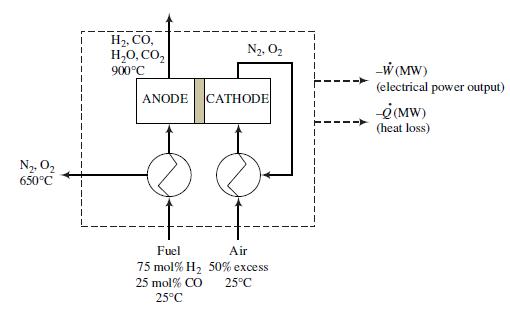
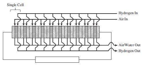
In the SOFC shown in the following figure, a mixture containing 75 mole% hydrogen and the balance carbon monoxide reacts with oxygen from air to produce water and carbon dioxide plus DC electricity. The overall process is shown in the following schematic diagram, and a device consisting of 10 single fuel cells stacked in series is shown in Problem 9.19.
The process functions as follows:
• Hydrogen and carbon monoxide at 25°C are preheated and fed to the anode compartments of the single cells, where they combine with oxygen ions that have come through membranes that separate the electrodes and form water and carbon dioxide plus free electrons. The membranes are permeable to oxygen ions but impermeable to electrons. The fractional conversions of H2 and CO are each 95.0%. The reaction products and unconsumed fuel are transported from the anode compartments to an incinerator.
• The electrons form at all but the last of the anodes of each cell and flow through a conducting plate to the cathode of the adjacent cell. The electrons from the last cell flow through an external circuit that delivers electricity to the devices being powered by the fuel cell and connects back to the cathode of the first cell.
• Fifty percent excess air at 25°C is preheated and fed to each cell cathode, where the oxygen in the air reacts with the electrons entering the cathode to produce the oxygen ions that permeate through the membrane to the cell anode. The exit streams from the cathodes are combined and pass through the air and fuel preheaters before being discharged to the atmosphere.
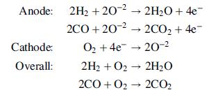
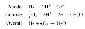
The following reactions occur in the SOFC:
A 1.00MW (maximum) SOFC is used to power an office building that has the following average electrical energy demand for each tenant when the building is occupied.
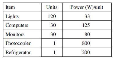
After normal business hours, an average of 5 computers, 5 monitors, and the refrigerator are left on by each tenant.
(a) Determine the total number of tenants in the office building whose offices can be powered by the 1.00MW SOFC.
(b) Determine the heat loss from the fuel cell in kW when the cell is putting out its full power output of 1MW, assuming a thermal efficiency of 60.0% (i.e., the electric power output is 60% of the total rate of enthalpy change for the unit).
(c) The fractional conversion of the CO and H2 fed to the fuel cell are each 95%. Determine the required input molar flow rate of the fuel. (Suggestion: Start by taking a basis of 100 mol fuel, then scale the process to the specified 1.00MWelectrical power output. Don’t forget that you know the thermal efficiency of the process.)
(d) Calculate the required fuel input molar flow rate after business hours.
Problem 9.19
Fuel cells have been proposed as an alternative energy technology for use in stationary and transportation applications. A fuel cell is an electrochemical device in which hydrogen reacts with oxygen from the air to produce water and DC electricity. The most flexible fuel cell design is the proton exchange membrane fuel cell (PEMFC). A 1-W PEMFC could be used for portable applications such as cellular telephones, and a 100-kW PEMFC could be used to power an automobile.
A schematic of a 10-cell stack of fuel cells connected in series is shown on the next page. Each cell consists of an anode (left block with lines sloping up and to the right), electrolyte membrane (center block with horizontal lines), and cathode (right block with line sloping down and to the right). The hydrogen and air are fed in parallel to each cell. Also, the exiting gas flows are collected in parallel.
The following reactions occur inside the PEMFC:
H2, CO, H,0, CO, N2, O2 -W (MW) (electrical power output) 900C ANODE CATHODE -e(MW) (heat loss) N2. O2 650C Fuel Air 75 mol% H2 50% excess 25 mol% CO 25C 25C
Step by Step Solution
3.42 Rating (168 Votes )
There are 3 Steps involved in it
a To determine the number of tenants that can be powered by the 100 MW SOFC we need to compare the electrical energy demand of the tenants with the po... View full answer

Get step-by-step solutions from verified subject matter experts