

Question: The telecommunication circuit shown in FIGURE CP32.71 has a parallel inductor and capacitor in series with a resistor. a. Use a phasor diagram to show
The telecommunication circuit shown in FIGURE CP32.71 has a parallel inductor and capacitor in series with a resistor.
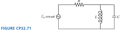
a. Use a phasor diagram to show that the peak current through the resistor is
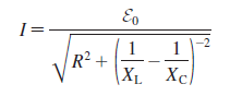
b. What is I in the limits ω ?? 0 and ω ?? ???c. What is the resonance frequency ω0? What is I at this frequency?
Ep cos wt C FIGURE CP32.71
Step by Step Solution
★★★★★
3.43 Rating (162 Votes )
There are 3 Steps involved in it
1 Expert Approved Answer
Step: 1 Unlock

Model The capacitor current leads the voltage by 90 The inductor current lags the voltage by 90 Visu... View full answer
Question Has Been Solved by an Expert!
Get step-by-step solutions from verified subject matter experts
Step: 2 Unlock
Step: 3 Unlock