

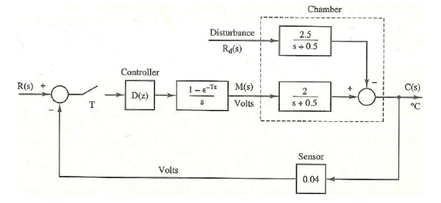
Shown in Figure P5-12 is the block diagram for the temperature control system for a large test
Fantastic news! We've Found the answer you've been seeking!
Question:
Shown in Figure P5-12 is the block diagram for the temperature control system for a large test chamber. This system is described in Problem 1-10. The disturbance shown is the model of the effects of opening the chamber door. The following transfer functions are defined. 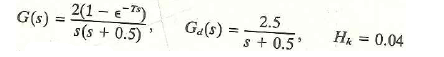 a) Derive the transfer function C(z)IR(z), in terms of the transfer functions just defined. b) With r(t) = 0, solve for the output function C(s) in terms of the disturbance input and the transfer functions just defined. c) Use superposition and the results of parts (a) and (b) to write the complete expression of C(z).
Figure P5-12 Chamber temperature control system.
Expert Answer:
a Find the transfer function of the block diagram for temperature control system The given transfer ... View the full answer

Related Book For 
Digital Systems Design Using Verilog
ISBN: 978-1285051079
1st edition
Authors: Charles Roth, Lizy K. John, Byeong Kil Lee
Posted Date:
