Question: The block diagram for an elevator controller for a building with two floors is shown in the following diagram. The inputs FB 1 and FB

The block diagram for an elevator controller for a building with two floors is shown in the following diagram. The inputs FB1and FB2are floor buttons in the elevator. The inputs CALL1and CALL2are call buttons in the hall. The inputs FS1and FS2are floor switches that output a 1 when the elevator is at the first or second floor landing. Outputs UP and DOWN control the motor, and the elevator is stopped when UP = DOWN = 0. N1and N2are flip-flops that indicate when the elevator is needed on the first or second floor. R1and R2are signals that reset these flip-flops. DO = 1 causes the door to open, and DC = 1 indicates that the door is closed. Draw an SM chart for the elevator controller (four states).

R2 FB, Storage circuit N1 R1 CALL, - FB2→ Storage Elevator + UP control circuit N2 CALL2– + DOWN circuit FS, FS2 DO

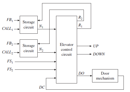
R2 FB, Storage circuit N1 R1 CALL, - FB2 Storage Elevator + UP control circuit N2 CALL2 + DOWN circuit FS, FS2 DO Door mechanism DC

Step by Step Solution

3.45 Rating (165 Votes )

There are 3 Steps involved in it

1 Expert Approved Answer
Step: 1 Unlock

F12 FS2 1 R2 D0 F22 N2 ... View full answer

blur-text-image
Question Has Been Solved by an Expert!

Get step-by-step solutions from verified subject matter experts

Step: 2 Unlock
Step: 3 Unlock

Students Have Also Explored These Related Digital Systems Design Questions!