

Question: 1 0 . 1 0 Given: The elevation view of the two - story wood - frame shearwall in Figure 1 0 . C .
Given: The elevation view of the twostory woodframe shearwall in Figure C The
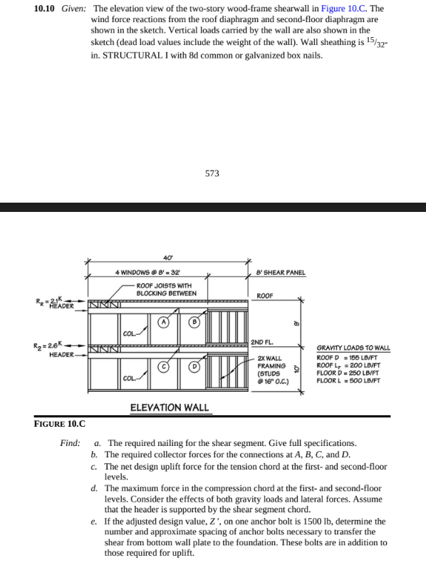
wind force reactions from the roof diaphragm and secondfloor diaphragm are
shown in the sketch. Vertical loads carried by the wall are also shown in the
sketch dead load values include the weight of the wall Wall sheathing is
in STRUCTURAL I with d common or galvanized box nails.
GRAVTY LOADS TO WALL
ROOF D LBMFT
ROOF L
FLOOR D LBFT
FLOOR L LBFT
ELEVATION WALL
FIGURE C
Find: The required nailing for the shear segment. Give full specifications.
b The required collector forces for the connections at and
c The net design uplift force for the tension chord at the first and secondfloor
levels.
d The maximum force in the compression chord at the first and secondfloor
levels. Consider the effects of both gravity loads and lateral forces. Assume
that the header is supported by the shear segment chord.
e If the adjusted design value, on one anchor bolt is determine the
number and approximate spacing of anchor bolts necessary to transfer the
shear from bottom wall plate to the foundation. These bolts are in addition to
those required for uplift.
Step by Step Solution
There are 3 Steps involved in it
1 Expert Approved Answer
Step: 1 Unlock

Question Has Been Solved by an Expert!
Get step-by-step solutions from verified subject matter experts
Step: 2 Unlock
Step: 3 Unlock