

Question: 1) clc clear all close all A = 0.01; % m^2 E = 60*10^9; % Pa F = 7*10^6; % N node = 6; %
1)
clc
clear all
close all
A = 0.01; % m^2
E = 60*10^9; % Pa
F = 7*10^6; % N
node = 6; % No- of nodes
DOF = 2; % DOF
TDOF = node*DOF; % Total DOF
coord = [0,0;0,8;4,4;6,2;8,0;4,0]; % coordinate of Nodes
Nelem = 9;
Elcon = [1,2;1,3;1,6;2,3;3,4;3,6;4,5;4,6;5,6]; % conecting elements
BCS=zeros(TDOF,DOF); % ?????
BCS(1,1)=1;
BCS(2,1)=1;
BCS(3,1)=1;
BCS(4,1)=1;
BCS(11,1)=1;
BCS(12,1)=1;
Ksys= zeros(TDOF,TDOF);
figure
hold on
for ielem=1:Nelem
line([coord(Elcon(ielem,1),1),coord(Elcon(ielem,2),1)],[coord(Elcon(ielem,1),2),
coord(Elcon(ielem,2),2)],'linestyle','-')
end
xlabel({'Position x'});
ylabel({'Position Y'});
% build the ss stiffenis matrix
for ielem = 1: Nelem
node1 = Elcon(ielem,1);
node2 = Elcon(ielem,2);
dx=coord(node2,1)-coord(node1,1);
dy=coord(node2,2)-coord(node1,2);
L=sqrt(dx^2+dy^2);
c=dx/L;
s=dy/L;
T1=[c,s;-s,c];
% initilize the transformation matrix
T=zeros(4);
T(1:2,1:2)=T1;
T(3:4,3:4)=T1;
% stiffness matrix m local coordinate sys
K=(A*E/L)*[1,0,-1,0 ; 0,0,0,0 ; -1,0,1,0 ; 0,0,0,0];
% stiffness in global coordinatesys
Kelem=transpose(T)*K*T;
%Assembly of element siffness matrix
elementDOF=[2*node1-1,2*node1,2*node2-1,2*node2];
Ksys(elementDOF,elementDOF) = Ksys(elementDOF,elementDOF)+Kelem;
end
% sys local vector
Psys=zeros(TDOF,1);
psys(10,1)=-F;
%sys vector of nodal global displacement
dsys=zeros(TDOF,1);
% Define boundry condition
%applying cmrsing
for ielem=1:TDOF
if BCS(ielem,1)==1
Ksys(ielem,1:TDOF)=0;
Ksys(1:TDOF,ielem)=0;
Ksys(ielem,ielem)=1;
end
end
%global displacement vectors
dsys=Ksys\Psys;
%system force vector
Reac=zeros(TDOF,1);
% initial at the stress and force matrix
Stress=zeros(Nelem,1);
Force=zeros(Nelem,1);
for ielem=1:Nelem
node1 = Elcon(ielem,1);
node2 = Elcon(ielem,2);
elementDOF=[2*node1-1,2*node1,2*node2-1,2*node2];
uglob=dsys(elementDOF);
% dx=coord(node2,1)-coord(node1,1);
% dy=coord(node2,2)-coord(node1,2);
dx=coord(node2,1)-coord(node1,1);
dy=coord(node2,2)-coord(node1,2);
L=sqrt(dx^2+dy^2);
c=dx/L;
s=dy/L;
T1=[c,s;-s,c];
T=zeros(4);% ???
T(1:2,1:2)=T1;
T(3:4,3:4)=T1;
uloc= T*uglob;
%strain displacement monitor
B=[-1/L,0,1/L,0];
stress(ielem,1)=E*B*uglob;
Force(ielem,1)=A*stress(ielem,1)% ????
%local Element Force Vector
Floc=[-Force(ielem,1);0;Force(ielem,1);0]
%Global Element Force Vector
Fglob=transpose(T)*Floc
Reac(elementDOF)=Reac(elementDOF)+Fglob
end
Result :
Force =
0
0
0
0
0
0
0
0
0
Floc =
0
0
0
0
Fglob =
0
0
0
0
Reac =
0
0
0
0
0
0
0
0
0
0
0
0
Sometings goes wrong That I don't know where ? It should gives the result of forces
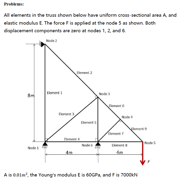
Problems: All elements in the truss shown below have uniform cross-sectional area A, and elastic modulus E. The force F is applied at the node 5 as shown. Both displacement components are zero at nodes 1, 2, and 6. Node 2 Element 2 Element 1 Node 3 Element 6 Element 3 Node 4 Element 5 ement 9 Element 7 Element 4 Node 5 Node 6 Element 8 Node 1 4 A is 0.01m2, the Young's modulus E is 60GPa, and F is 7000kN Problems: All elements in the truss shown below have uniform cross-sectional area A, and elastic modulus E. The force F is applied at the node 5 as shown. Both displacement components are zero at nodes 1, 2, and 6. Node 2 Element 2 Element 1 Node 3 Element 6 Element 3 Node 4 Element 5 ement 9 Element 7 Element 4 Node 5 Node 6 Element 8 Node 1 4 A is 0.01m2, the Young's modulus E is 60GPa, and F is 7000kN
Step by Step Solution
There are 3 Steps involved in it

Get step-by-step solutions from verified subject matter experts