

Question: 1. Consider the function given below, solve: e f g h F = (X+Y)(X + XY)Z + X(Y+Z) + XY + XYZ (a) Simplify
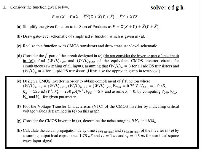
1. Consider the function given below, solve: e f g h F = (X+Y)(X + XY)Z + X(Y+Z) + XY + XYZ (a) Simplify the given function to its Sum of Products as F =Z(X+Y) + X(Y + Z). (b) Draw gate-level schematic of simplified F function which is given in (a). (c) Realize this function with CMOS transistors and draw transistor-level schematic. (d) Consider the f part of the circuit designed in (c) (do not consider the inverter part of the circuit in (c)), find (W/L)neq and (W/L)pea of the equivalent CMOS inverter circuit for simultaneous switching of all inputs, assuming that (W/L)n = 3 for all nMOS transistors and (W/L), = 4 for all pMOS transistor. (Hint: Use the approach given in textbook.) (e) Design a CMOS inverter in order to obtain complement of f function where (W/L)ninv = (W/L)n.egs (W/L)p.inv = (W/L)peqs Vron = 0.75 V, Vro.p = -0.45, k = 155 A/V, k = 250 A/V, VoD = 5 V and assume = 0, by computing VOH. VOL. VIL and VIH for given parameters. (f) Plot the Voltage Transfer Characteristic (VTC) of the CMOS inverter by indicating critical voltage values determined in (e) on this graph. (g) Consider the CMOS inverter in (e), determine the noise margins NM, and NMH- (h) Calculate the actual propagation delay time TPHL actual and TPLH, actual of the inverter in (e) by assuming output load capacitance 1.75 pF and Ty = 1 ns and T = 0.5 ns for non-ideal square wave input signal.
Step by Step Solution
3.47 Rating (177 Votes )
There are 3 Steps involved in it

Get step-by-step solutions from verified subject matter experts