

Question: 1 . Construct the circuit shown in Figure ( 1 b ) using the breadboard with jumper - wires. Make sure that the
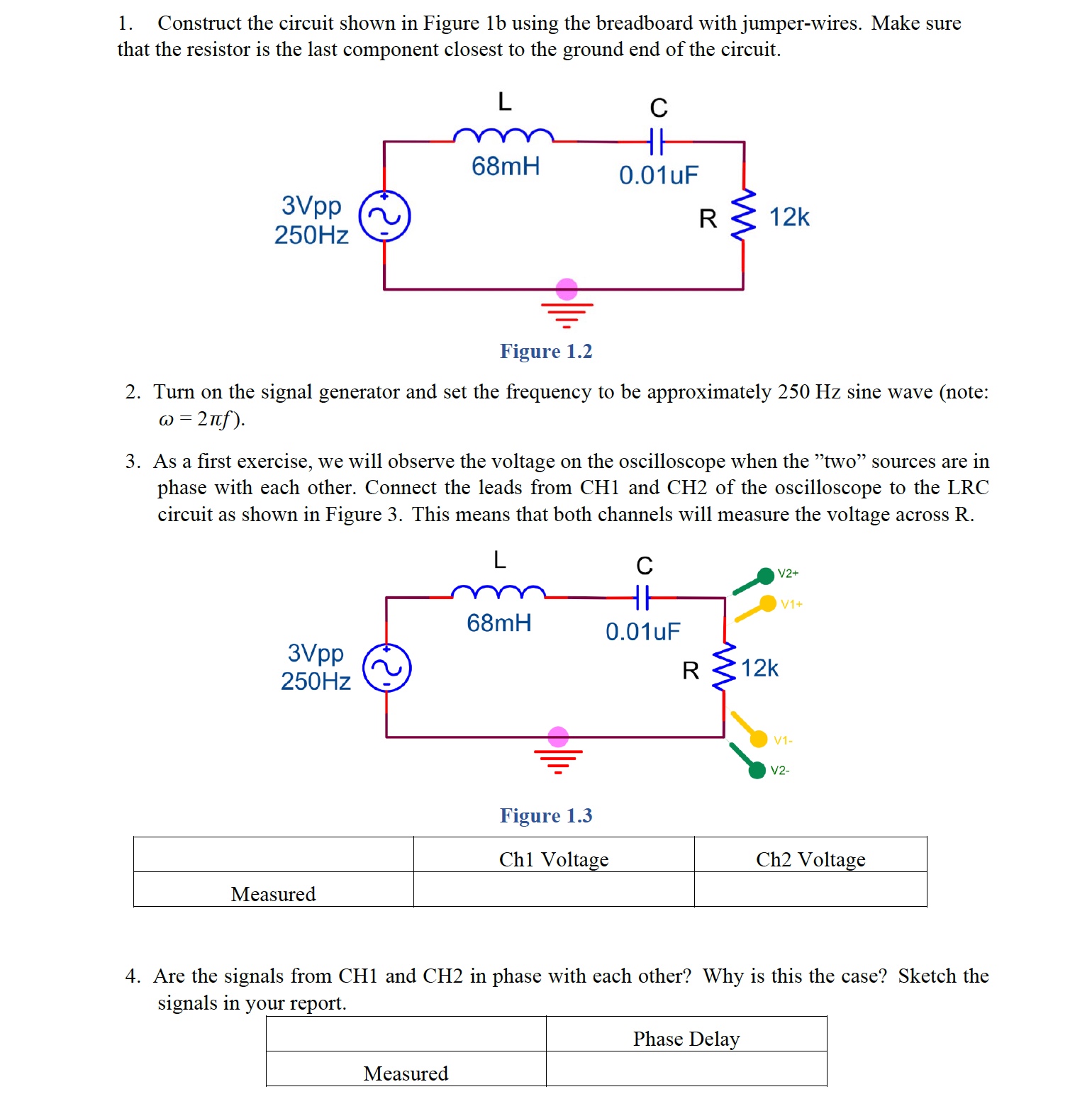
Construct the circuit shown in Figure b using the breadboard with jumperwires. Make sure that the resistor is the last component closest to the ground end of the circuit.
Turn on the signal generator and set the frequency to be approximately Hz sine wave note: omegapi f
As a first exercise, we will observe the voltage on the oscilloscope when the "two" sources are in phase with each other. Connect the leads from CH and CH of the oscilloscope to the LRC circuit as shown in Figure This means that both channels will measure the voltage across R
Are the signals from CH and CH in phase with each other? Why is this the case? Sketch the signals in your report. Change the display selector from y to x y If both x and y are in phase with each other they both reach their peaks and valleys at the same instant the oscilloscope should display a straight line inclined at an angle degrees if both inputs have the same magnitude and calibration scale Verify this. Just as you directly observed the waveform in Procedure this is another technique to check if the two signals are in phase with each other. This display is known as a Lissajous figure.
Change the time base back to YT Disconnect CH from the circuit and connect it as shown in Figure In this position, CH is still measuring the voltage across the resistor VR but CH is now measuring the voltage across all three components VRLC
Are the two signals in phase with each other? Does VR L C lead or lag VR and by how much?
Step by Step Solution
There are 3 Steps involved in it
1 Expert Approved Answer
Step: 1 Unlock

Question Has Been Solved by an Expert!
Get step-by-step solutions from verified subject matter experts
Step: 2 Unlock
Step: 3 Unlock