

Question: 1. Design the truth table for new specification 2. Use truth table to obtain logical expression for outputs 3. Find simplified logical expressions Design of
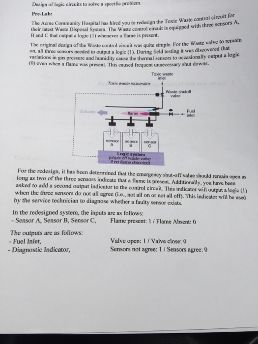
Design of logic circuits to solve a specific problem Pre-Lab: control circuit for The Acme Community Hospital has hired you to redesign the Toxic Waste their latest Waste Disposal System. The Waste control circuit is equipped with three sensors A, B and C that output a logic (1) whenever a flame is present The original design of the Waste control circuit was quite simple. For the Waste valve to on, all three sensors needed to output a logic (1). During variations in gas pressure and humidity cause the thermal sensors to occasionally output a (O) even when a flame was present. This caused frequent unnecessary shut downs field testing it was discovered that logic Toxic waste inlet Toxic waste incineralor Waste shutolf valve Fuel -inlet flame sensor sensorsensor (shuts off waste valve For the redesign, it has been determined that the emergency shut-off value should remain open as long as two of the three sensors indicate that a flame is present. Additionally, you have been asked to add a second output indicator to the control circuit. This indicator will output a logic() when the three sensors do not all agree (i.e., not all on or not all off). This indicator will be used by the service technician to diagnose whether a faulty sensor exists. In the redesigned system, the inputs are as follows: - Sensor A, Sensor B, Sensor C, Flame present: 1/Flame Absent:0 The outputs are as follows: - Fuel Inlet -Diagnostic Indicator, Valve open: 1/ Valve close: 0 Sensors not agree: 1 / Sensors agree: 0
Step by Step Solution
There are 3 Steps involved in it

Get step-by-step solutions from verified subject matter experts