

Question: 1 PID Controller and Its Practical Implementation A continuous - time PID controller is given by u ( t ) = K _ ( P
PID Controller and Its Practical Implementation
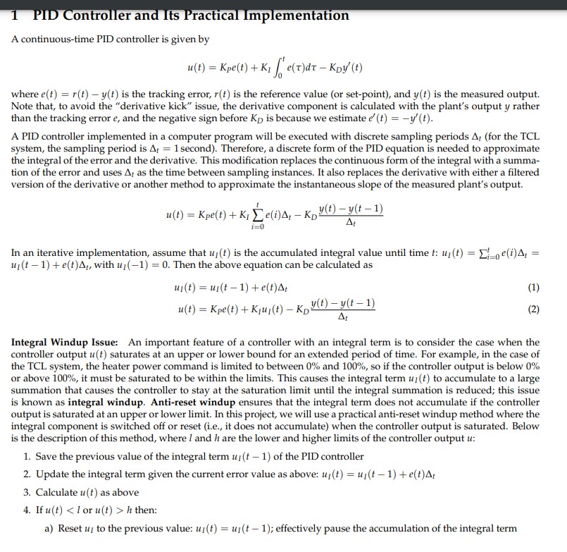
A continuoustime PID controller is given by
utKPetKIintt etau dtau KDyt
where etrtyt is the tracking error, rt is the reference value or setpoint and yt is the measured output.
Note that, to avoid the "derivative kick" issue, the derivative component is calculated with the plant's output y rather
than the tracking error e and the negative sign before KD is because we estimate etyt
A PID controller implemented in a computer program will be executed with discrete sampling periods Delta tDelta t secondDelta t as the time between sampling instances. It also replaces the derivative with either a filtered
version of the derivative or another method to approximate the instantaneous slope of the measured plant's output.
utKPetKIsumit eiDelta tKDytytDelta t
In an iterative implementation, assume that uIt is the accumulated integral value until time t:uItsumit eiDelta t
uItetDelta t with uI Then the above equation can be calculated as
uItuItetDelta t
utKPetKIuItKDytytDelta t
Integral Windup Issue: An important feature of a controller with an integral term is to consider the case when the
controller output ut saturates at an upper or lower bound for an extended period of time. For example, in the case of
the TCL system, the heater power command is limited to between and so if the controller output is below
or above it must be saturated to be within the limits This causes the integral term uIt to accumulate to a large
summation that causes the controller to stay at the saturation limit until the integral summation is reduced; this issue
is known as integral windup. Antireset windup ensures that the integral term does not accumulate if the controller
output is saturated at an upper or lower limit In this project, we will use a practical antireset windup method where the
integral component is switched off or reset ie it does not accumulate when the controller output is saturated. Below
is the description of this method, where l and h are the lower and higher limits of the controller output u :
Save the previous value of the integral term uIt of the PID controller
Update the integral term given the current error value as above: uItuItetDelta t
Calculate ut as above
If uthuIuItuItut or uth then:
a
but to the limit range lh :
utl if uth:
Return ut and uItwhich will be used in the next sampling time step
Tuning PID Controller for FOPDT Models
For tuning the PID parameters for an FOPDT model with the transfer function Kptau psetheta ps we will use the following
methods:
PI control:
PIIMC method: tau cmaxtau ptheta p;KcKptau ptheta ptau c;tau Itau p
PIITAE method: KcKptheta ptau p;tau Itau ptheta ptau p
PID control: PIDIMC method:
tau cmaxtau ptheta p;KcKptau ptheta ptau ctheta p;tau Itau ptheta p;tau Dtau ptheta ptau ptheta p
Then, the PID parameters are given by:
KPKc;KIKctau I;KDKctau D
Step by Step Solution
There are 3 Steps involved in it
1 Expert Approved Answer
Step: 1 Unlock

Question Has Been Solved by an Expert!
Get step-by-step solutions from verified subject matter experts
Step: 2 Unlock
Step: 3 Unlock