

Question: 2 2 . For the positive edge - triggered J - K flip - flop with preset and clear shown in Figure 6 . 2
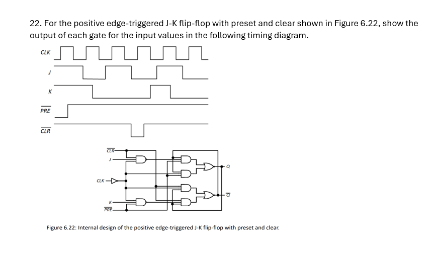
For the positive edgetriggered JK flipflop with preset and clear shown in Figure show the output of each gate for the input values in the following timing diagram.
Figure : Internal design of the positive edgetriggered JK flipflop with preset and clear.
Step by Step Solution
There are 3 Steps involved in it
1 Expert Approved Answer
Step: 1 Unlock

Question Has Been Solved by an Expert!
Get step-by-step solutions from verified subject matter experts
Step: 2 Unlock
Step: 3 Unlock