

Question: 2 . 4 Design a 4 - bit parallel - in parallel - out ( PIPO ) right - shift register with D flip -
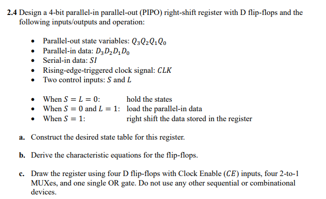
Design a bit parallelin parallelout PIPO rightshift register with D flipflops and the
following inputsoutputs and operation:
Parallelout state variables:
Parallelin data:
Serialin data:
Risingedgetriggered clock signal:
Two control inputs: and
When : hold the states
When and : load the parallelin data
When : right shift the data stored in the register
a Construct the desired state table for this register.
b Derive the characteristic equations for the flipflops.
c Draw the register using four D flipflops with Clock Enable CE inputs, four to
MUXes, and one single OR gate. Do not use any other sequential or combinational
devices.
Step by Step Solution
There are 3 Steps involved in it
1 Expert Approved Answer
Step: 1 Unlock

Question Has Been Solved by an Expert!
Get step-by-step solutions from verified subject matter experts
Step: 2 Unlock
Step: 3 Unlock