

Question: 2) A Hexadecimal to 7-segment display controller will be designed. Block diagram of the complete system is shown in Fig. 1. In order to
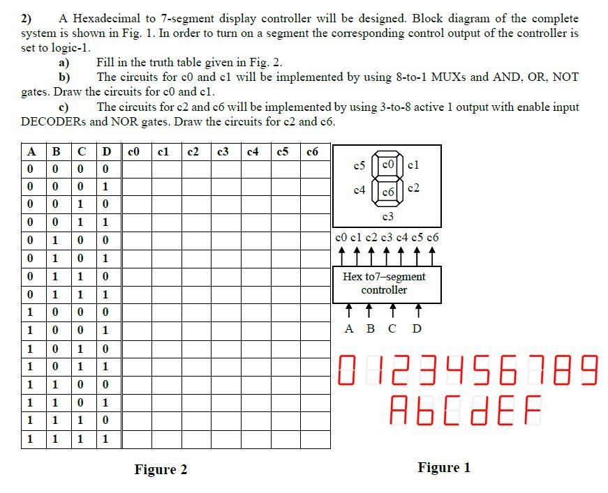
2) A Hexadecimal to 7-segment display controller will be designed. Block diagram of the complete system is shown in Fig. 1. In order to turn on a segment the corresponding control output of the controller is set to logic-1. Fill in the truth table given in Fig. 2. a) The circuits for co and cl will be implemented by using 8-to-1 MUXS and AND, OR, NOT b) gates. Draw the circuits for c0 and cl. c) The circuits for c2 and c will be implemented by using 3-to-8 active 1 output with enable input DECODERS and NOR gates. Draw the circuits for c2 and c6. A BCD co 0 0 0 0 0 0 0 1 0 0 1 0 0 1 0 1 1 0 1 11 0 1 1 1 00 0 1 0 0 1 0 1 0 1 10 0 cl c2 c3 c4 c5 c c5 c | c1 c4 c6 c2 c3 1 c0 cl c2 c3 c4 c5 c6 Hex to7-segment controller 1 D 1 0 123456789 A6CDEF 1 1 1 1 1 1 1 1 1 1 1 Figure 2 Figure 1 1.
Step by Step Solution
3.44 Rating (154 Votes )
There are 3 Steps involved in it
B CDICO C1 C2 C3 4 CSC6 01 ... View full answer

Get step-by-step solutions from verified subject matter experts