

Question: 2 . Design an asynchronous counter based on the state diagram given in Figure 1 . The design should use only positive - going transition
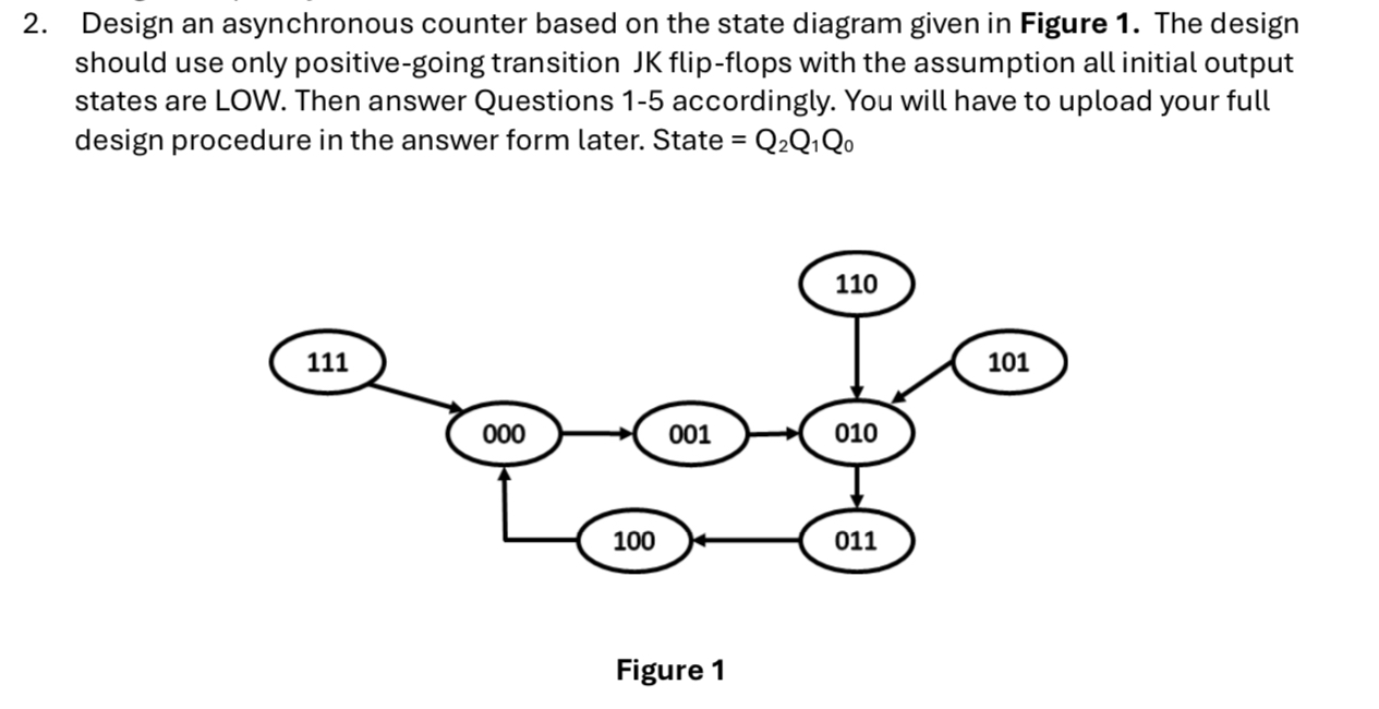
Design an asynchronous counter based on the state diagram given in Figure The design should use only positivegoing transition JK flipflops with the assumption all initial output states are LOW. Then answer Questions accordingly. You will have to upload your full design procedure in the answer form later. State mathrmQmathrmQmathrmQ
Figure
Please dont use Chat GPT and make it clear
Step by Step Solution
There are 3 Steps involved in it
1 Expert Approved Answer
Step: 1 Unlock

Question Has Been Solved by an Expert!
Get step-by-step solutions from verified subject matter experts
Step: 2 Unlock
Step: 3 Unlock