

Question: 2 . For the state machine described by the following state table, with input ( s ) , output ( f
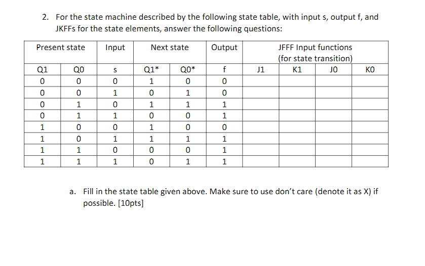
For the state machine described by the following state table, with input s output f and JKFFs for the state elements, answer the following questions:
begintabularcccccccccc
hline multicolumnc Present state & Input & multicolumnc Next state & Output & multicolumncbegintabularc
JFFF Input functions
for state transition
endtabular
hline Q & Q & s & Q & QO & f & J & K & J & K
hline & & & & & & & & &
hline & & & & & & & & &
hline & & & & & & & & &
hline & & & & & & & & &
hline & & & & & & & & &
hline & & & & & & & & &
hline & & & & & & & & &
hline & & & & & & & & &
hline
endtabular
a Fill in the state table given above. Make sure to use don't care denote it as X if possible. pts c Draw its state transition diagram. pts
d Find JKFF input functions in mSOP form. pts
e Draw logic diagram of the given state machine. pts
Step by Step Solution
There are 3 Steps involved in it
1 Expert Approved Answer
Step: 1 Unlock

Question Has Been Solved by an Expert!
Get step-by-step solutions from verified subject matter experts
Step: 2 Unlock
Step: 3 Unlock