

Question: 2) We designed the 4-bit multiplier Controller Unit hardware as follows: Sequence Controller External inputs L Clock 3-bit counter C) Reset E 1 0 CO,
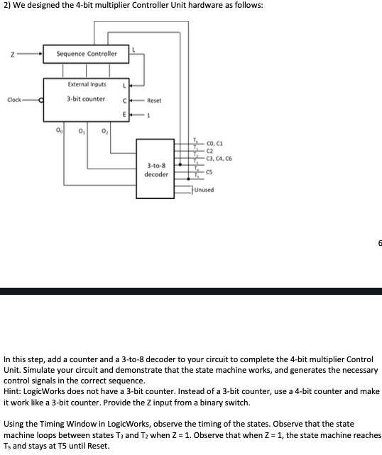
2) We designed the 4-bit multiplier Controller Unit hardware as follows: Sequence Controller External inputs L Clock 3-bit counter C) Reset E 1 0 CO, CH 3-to-8 decoder C3, C4, C6 cs Unused 6 In this step, add a counter and a 3-to-8 decoder to your circuit to complete the 4-bit multiplier Control Unit Simulate your circuit and demonstrate that the state machine works, and generates the necessary control signals in the correct sequence. Hint: LogicWorks does not have a 3-bit counter. Instead of a 3-bit counter, use a 4-bit counter and make it work like a 3-bit counter. Provide the input from a binary switch. Using the Timing Window in LogicWorks, observe the timing of the states. Observe that the state machine loops between states T3 and T2 when Z = 1. Observe that when Z = 1, the state machine reaches Ts and stays at T5 until Reset. 2) We designed the 4-bit multiplier Controller Unit hardware as follows: Sequence Controller External inputs L Clock 3-bit counter C) Reset E 1 0 CO, CH 3-to-8 decoder C3, C4, C6 cs Unused 6 In this step, add a counter and a 3-to-8 decoder to your circuit to complete the 4-bit multiplier Control Unit Simulate your circuit and demonstrate that the state machine works, and generates the necessary control signals in the correct sequence. Hint: LogicWorks does not have a 3-bit counter. Instead of a 3-bit counter, use a 4-bit counter and make it work like a 3-bit counter. Provide the input from a binary switch. Using the Timing Window in LogicWorks, observe the timing of the states. Observe that the state machine loops between states T3 and T2 when Z = 1. Observe that when Z = 1, the state machine reaches Ts and stays at T5 until Reset
Step by Step Solution
There are 3 Steps involved in it

Get step-by-step solutions from verified subject matter experts