

Question: 4.2 The basic single-cycle MIPS implementation in Figure 4.2 can only implement some instructions. New instructions can be added to an existing Instruction Set Architecture
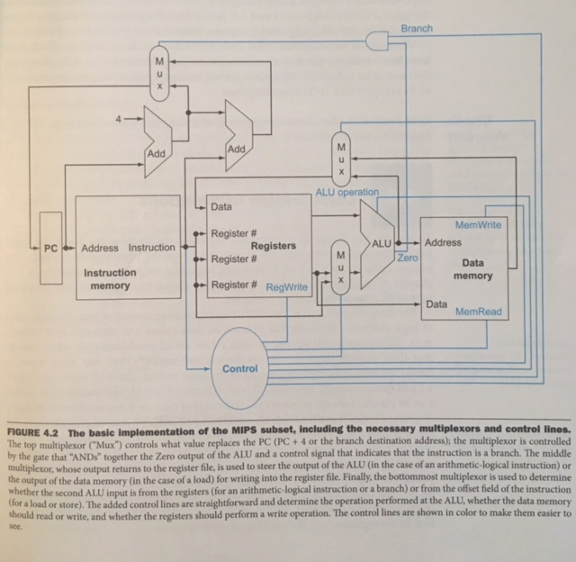
4.2 The basic single-cycle MIPS implementation in Figure 4.2 can only implement some instructions. New instructions can be added to an existing Instruction Set Architecture (ISA), but the decision whether or not to do that depends, among other things, on the cost and complexity the proposed addition introduces into the processor datapath and control. The first three problems in this exercise refer to the new instruction:
Instruction: LWI Rt, Rd (Rs)
Interpretation: Reg [Rt] = Mem[ Reg [Rd] + Reg [Rs] ]
4.2.1 Which existing blocks (if any) can be used for this instruction?
4.2.2 Which new functional blocks (if any) do we need for this instruction?
4.2.3 What new signals do we need (if any) from the control unit to support this instruction?
Branch ALU operation Lo Data MemWrite pm Register # PC - Address Instruction Registers ADALUTH Address - Register # Data Instruction memory memory - Register # Regwrite Data MemRead See Control FIGURE 4.2 The basic implementation of the MIPs subset, including the necessary multiplexors and control lines. The top multiplexer Mua) controls what value replaces the PC (PC +for the branch destination address the multiplexor is controlled by the gate that "AND together the zero output of the AU and a control signal that indicates that the instruction is a branch. The middle multipleton, whose output returns to the register file, is used to steer the output of the AL (in the case of an arithmetic logical instruction or is used the output of the data memory (in the case of a load) for writing into the register file. Finally, the bottommest multiplexer to determine Whether the second AL input is from the registers (for an arithmetic logical instruction or a branch) or from the offset field of the instruction ALU, whether data memor for a load or store. The added control lines are straightforward and determine the operation performed at the the hould read or writeand whether the registers should perform a write operation. The control lines are shown in color to make them easier to
Step by Step Solution
There are 3 Steps involved in it

Get step-by-step solutions from verified subject matter experts