

Question: 5 1 timescale ins/1ps 2 // Clock Devider 3 module testbench: reg clk 0; 6 reg rst-o; 7 wire clk_div; 8 9 10 // Instantiate
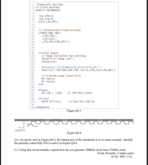
5 1 timescale ins/1ps 2 // Clock Devider 3 module testbench: reg clk 0; 6 reg rst-o; 7 wire clk_div; 8 9 10 // Instantiate clock Divider 11 CikDivider DUT 12 .clkclk). 13 rst(rst), 14 cik_div clk_div)); 15 16 17 18 initial begin // Dump variables for editing Sdumpfile("dump. vcd"); 21 Sdumpvars: $display("\t\ttime\tclk\trst\tclk_div"); Smonitor ("%d\t\txb\t%d".Stime.clk.rst.clk_div): // Provide some input bits #1 rst-1; 28 #7 rst=0; end always #5 clk = clk: 100 Mhz clock initial #120 Sfinish: // Run for 120 ns 37 endmodule Figure 04.3 19 20 488 .000 clk clk div C310 Figure 24.4 (iv) As can be seen in Figure Q4.3, the timing unit of the simulation is in ns (nano second). Identify the period(s) when EQ(=EN) is active in Figure 24.4. (v) Using this circuit module, explain how do you generate 100KHz clock from 33MHz clock. (Total 10 marks, 2 marks each) (CO2/PO3/C3)
Step by Step Solution
There are 3 Steps involved in it

Get step-by-step solutions from verified subject matter experts