

Question: (5 pts) You are asked to build a digital logic circuit for a security alarm system. The system has four Motion Sensors which indicate the
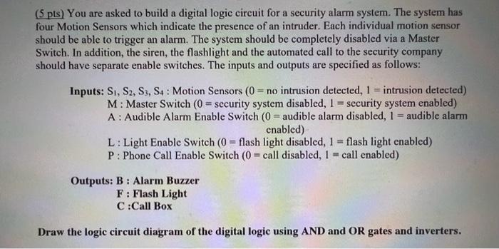
(5 pts) You are asked to build a digital logic circuit for a security alarm system. The system has four Motion Sensors which indicate the presence of an intruder. Each individual motion sensor should be able to trigger an alarm. The system should be completely disabled via a Master Switch. In addition, the siren, the flashlight and the automated call to the security company should have separate enable switches. The inputs and outputs are specified as follows: Inputs: S1,S2,S3,S4 : Motion Sensors (0= no intrusion detected, 1= intrusion detected) M : Master Switch (0= security system disabled, 1= security system enabled ) A : Audible Alarm Enable Switch (0= audible alarm disabled, 1 = audible alarm enabled) L : Light Enable Switch (0= flash light disabled, 1= flash light enabled) P : Phone Call Enable Switch (0= call disabled, 1= call enabled ) Outputs: B : Alarm Buzzer F : Flash Light C :Call Box Draw the logic circuit diagram of the digital logic using AND and OR gates and inverters
Step by Step Solution
There are 3 Steps involved in it

Get step-by-step solutions from verified subject matter experts