

Question: 8 . 2 Given the circuit diagram below with one input x and one output y . a . Complete the following Output and State
Given the circuit diagram below with one input and one output
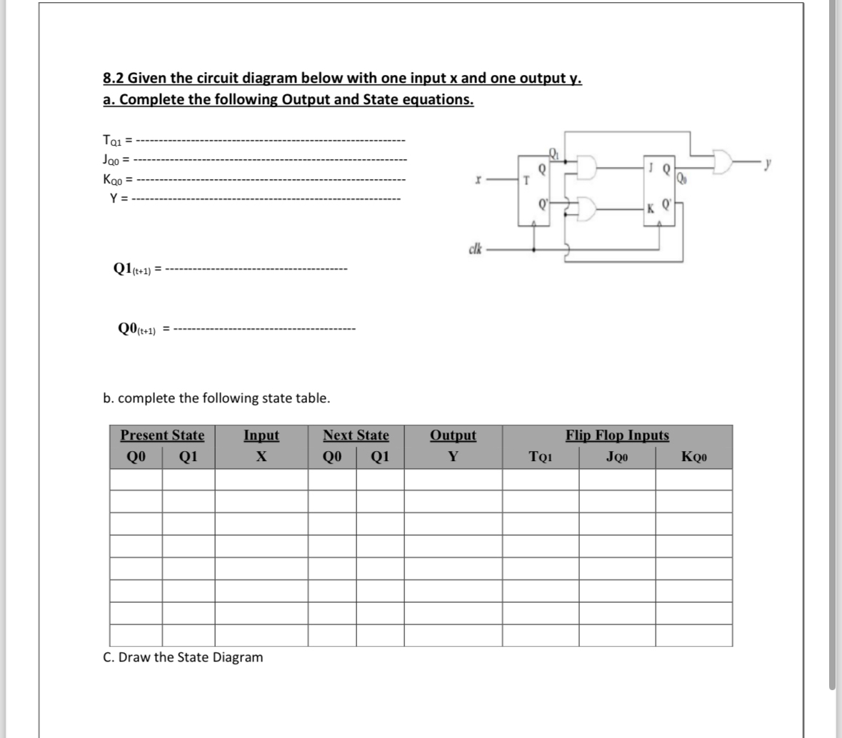
a Complete the following Output and State equations.
Q
b complete the following state table.
tablePresent State,Input,Output,Flip Flop InputsTQJQKQ
C Draw the State Diagram
Step by Step Solution
There are 3 Steps involved in it
1 Expert Approved Answer
Step: 1 Unlock

Question Has Been Solved by an Expert!
Get step-by-step solutions from verified subject matter experts
Step: 2 Unlock
Step: 3 Unlock