

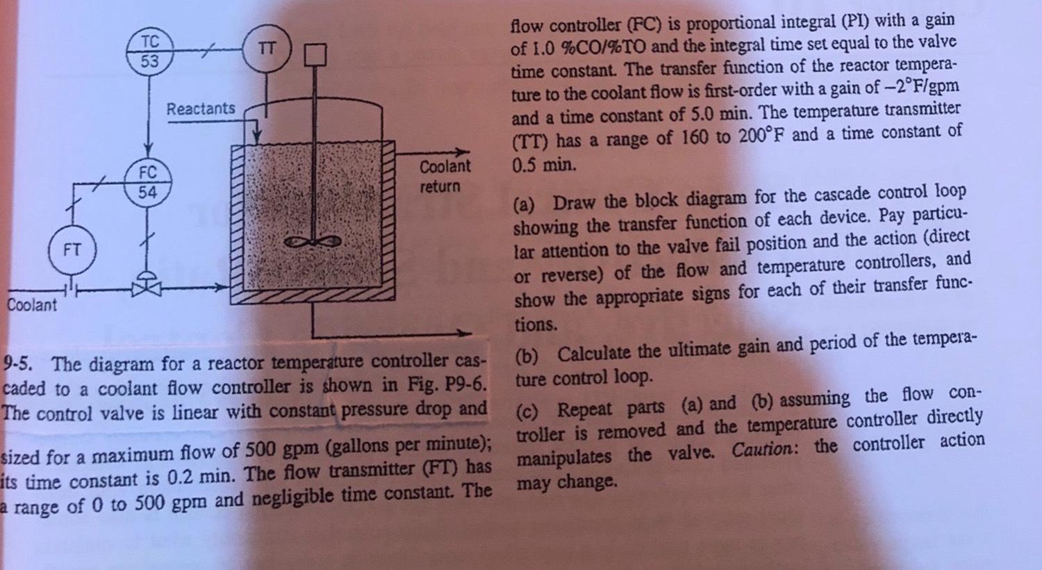
Question: 9 . 5 . The diagram for a reactor temperature controller cascaded to a coolant flow controller is shown in Fig. P 9 - 6
The diagram for a reactor temperature controller cascaded to a coolant flow controller is shown in Fig. P The control valve is linear with constant pressure drop and
sized for a maximum flow of gallons per minute; its time constant is min. The flow transmitter FT has range of to and negligible time constant. The
flow controller FC is proportional integral PI with a gain of and the integral time set equal to the valve time constant. The transfer function of the reactor temperature to the coolant flow is firstorder with a gain of and a time constant of min. The temperature transmitter TT has a range of to and a time constant of min.
a Draw the block diagram for the cascade control loop showing the transfer function of each device. Pay particular attention to the valve fail position and the action direct or reverse of the flow and temperature controllers, and show the appropriate signs for each of their transfer functions.
b Calculate the ultimate gain and period of the temperature control loop.
c Repeat parts a and b assuming the flow controller is removed and the temperature controller directly manipulates the valve. Caution: the controller action may change.
Step by Step Solution
There are 3 Steps involved in it
1 Expert Approved Answer
Step: 1 Unlock

Question Has Been Solved by an Expert!
Get step-by-step solutions from verified subject matter experts
Step: 2 Unlock
Step: 3 Unlock