

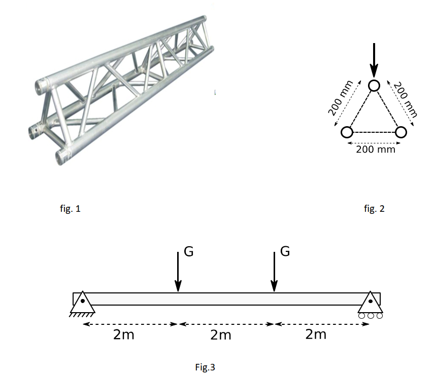
Question: A beam ( length , L = 6 m ) is constructed out as a truss system, as shown on figure 1 . The hollow,
A beam length L m is constructed out as a truss system, as shown on figure The hollow,
circular longitudinal beams have an outer diameter equal to mm and a wall thickness of mm They are
made out of Aluminum E GPa and maximal allowable normal stress sigma max MPa The centerline of
these horizontal beams is located on distance of mm between each other. The influence of the
connecting ie nonhorizontal beams on the moment of inertia can be neglected figure The beam can
be considered as simply supported and is subjected to two equal loads G which occur at a distance of L
from each support, as indicated on figure
a Draw the shear force and bending moment diagrams for this beam and give a formula for each
relevant point in these diagrams?
b What is the maximum allowable value of G
c Where does the maximum deformation occur in this beams? How large is this deformation if G
equals Nfig.
fig.
Fig.
Step by Step Solution
There are 3 Steps involved in it
1 Expert Approved Answer
Step: 1 Unlock

Question Has Been Solved by an Expert!
Get step-by-step solutions from verified subject matter experts
Step: 2 Unlock
Step: 3 Unlock