

Question: A closed loop feed-back control system is represented by the following block diagram (this is Figure 11.8, page 178 of Textbook): Figure 11.8 Standard block
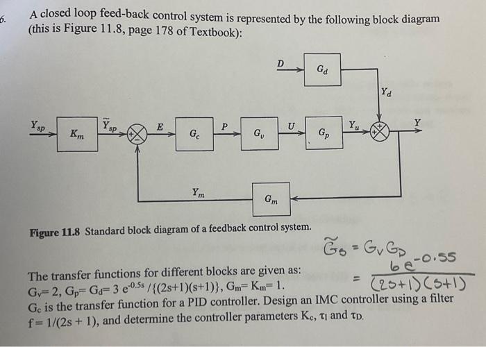
A closed loop feed-back control system is represented by the following block diagram (this is Figure 11.8, page 178 of Textbook): Figure 11.8 Standard block diagram of a feedback control system. The transfer functions for different blocks are given as: Gv=2,Gp=Gd=3e0.5s/{(2s+1)(s+1)},Gm=Km=1 Gs=GvGp=(2s+1)(s+1)6e0.55 Gc is the transfer function for a PID controller. Design an IMC controller using a filter f=1/(2s+1), and determine the controller parameters Kc,l and D A closed loop feed-back control system is represented by the following block diagram (this is Figure 11.8, page 178 of Textbook): Figure 11.8 Standard block diagram of a feedback control system. The transfer functions for different blocks are given as: Gv=2,Gp=Gd=3e0.5s/{(2s+1)(s+1)},Gm=Km=1 Gs=GvGp=(2s+1)(s+1)6e0.55 Gc is the transfer function for a PID controller. Design an IMC controller using a filter f=1/(2s+1), and determine the controller parameters Kc,l and D
Step by Step Solution
There are 3 Steps involved in it

Get step-by-step solutions from verified subject matter experts