

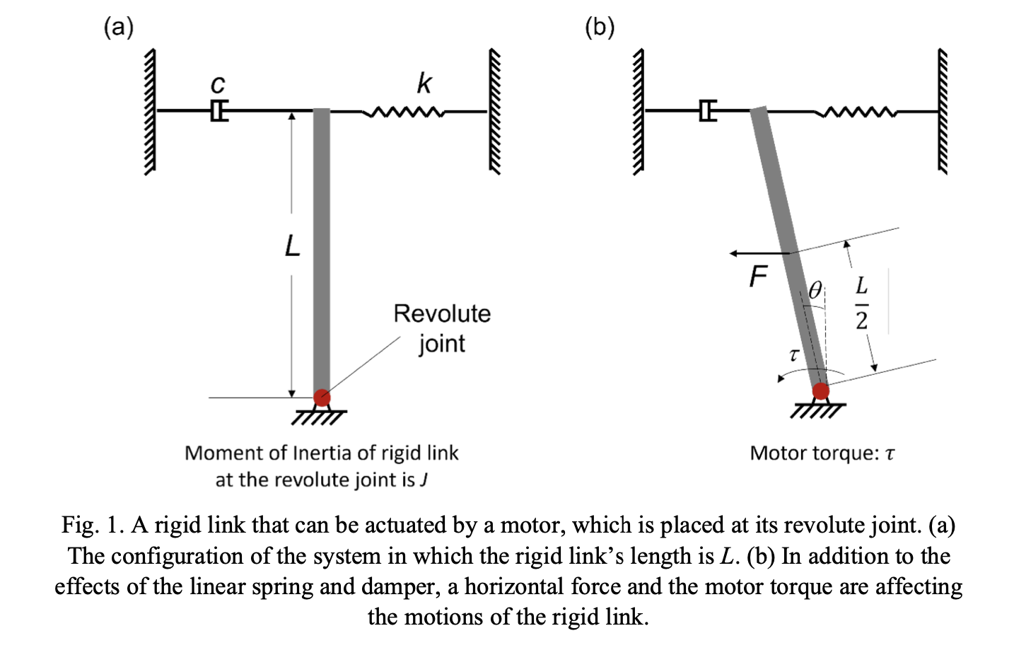
Question: ( a ) Figure 1 shows a rigid link in which its free end is connected to a linear spring and a linear damper. The
a Figure shows a rigid link in which its free end is connected to a linear spring and a linear damper. The length of the rigid link is L while the springs constant and damping coefficient are k and c respectively. To actuate this rigid link, we have mounted a motor at its revolute joint and its moment of inertia at the joint is given as J The torque supplied by the motor is given as while there is another horizontal force f which is applied at the centre of the rigid link. Assuming zero initial conditions, derive and draw out the block diagram components of this system in which the output of the system is the angular displacement generated by the rigid link We can assume that is small and ignore gravity.
marksb Determine the DC gain, natural frequency and damping ratio of the system. marks
Can you help me draw the block diagram clearly prefer if its on a physical paper
Step by Step Solution
There are 3 Steps involved in it
1 Expert Approved Answer
Step: 1 Unlock

Question Has Been Solved by an Expert!
Get step-by-step solutions from verified subject matter experts
Step: 2 Unlock
Step: 3 Unlock