

Question: a) Realize the next state logic and the output logic of this state machine using minimum amount of traditional gates (ANDs, ORs, & NOTs.) Draw
a) Realize the next state logic and the output logic of this state machine using minimum amount of traditional gates (ANDs, ORs, & NOTs.) Draw the complete circuit diagram.
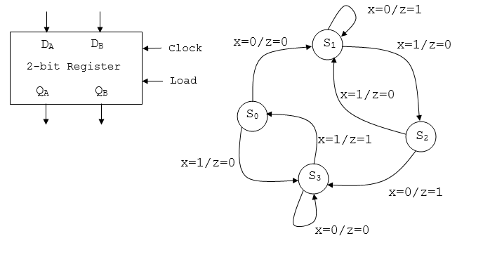
b) Realize the next state logic and the output logic of this state machine using 4:1 Multiplexers and other gates. For each of the multiplexers, connect QA to select input S1 and QB to select input S0. Draw the complete circuit diagram.
c) Realize the next state logic and the output logic of this state machine using a 3:8 Decoder and three OR gates. Draw the complete circuit diagram.
x-0/2=1 DA DB Clock x-0/z-0 S1 x-1/z-0 2-bit Register Load QA QB X-1/z-0 So x-1/z-1 S2 x-1/z-0 x-0/2-0 x-0/2=1 DA DB Clock x-0/z-0 S1 x-1/z-0 2-bit Register Load QA QB X-1/z-0 So x-1/z-1 S2 x-1/z-0 x-0/2-0
Step by Step Solution
There are 3 Steps involved in it

Get step-by-step solutions from verified subject matter experts