

Question: Consider the following behavior of a sequential logic. A state machine for this behavior has one input named X, one output named Z and two
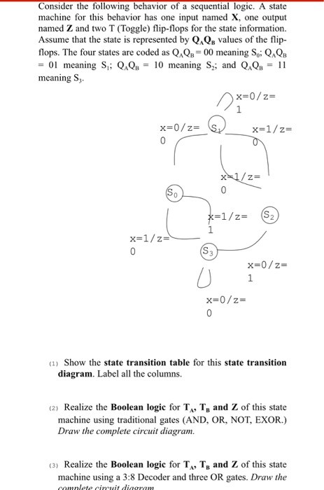
Consider the following behavior of a sequential logic. A state machine for this behavior has one input named X, one output named Z and two T (Toggle) flip-flops for the state information. Assume that the state is represented by Q&QB values of the flip- flops. The four states are coded as Q&QB=00 meaning S.; Q&QB = 01 meaning S; Q.Qs = 10 meaning Sy; and Q.Qs = 11 meaning S. 2X=0/2= x=0/z= _ x=1/2= x=1/z= x=1/z= S2 x=1/z= x=0/2= x=0/2= (1) Show the state transition table for this state transition diagram. Label all the columns. (2) Realize the Boolean logic for T, T. and Z of this state machine using traditional gates (AND, OR, NOT, EXOR.) Draw the complete circuit diagram. (3) Realize the Boolean logic for T, T, and Z of this state machine using a 3:8 Decoder and three OR gates. Draw the camnlete circuit diagram
Step by Step Solution
There are 3 Steps involved in it

Get step-by-step solutions from verified subject matter experts