

Question: Consider the following behavior of a sequential logic. A state machine for this behavior will have one input named X , one output named Z
Consider the following behavior of a sequential logic. A state machine for this behavior will have one input named X, one output named Z, and a 2-bit register (using D-type flip-flops) for state information. Assume that the state is represented by the Q1Q0 signals of the register.
The four states are coded as: Q1Q0 = 00 means S0; Q1Q0 = 01 means S1; Q1Q0 = 10 means S2; and Q1Q0 = 11 means S3.
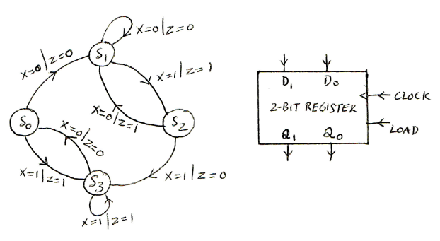
I. Begin by completing a state transition table based on the state diagram shown above.
II. Realize the next state logic and the output logic of this state machine using a minimum amount of traditional gates (ANDs, ORs, and NOTs). Draw and test the complete circuit in Logisim, clearly label all inputs and outputs, and attach your completed work as a Logisim circuit file.
III. Realize the next state logic and the output logic of this state machine using 4:1 multiplexers and other gates. Use the state variables Q1Q0 as the multiplexer selects. Draw and test the complete circuit in Logisim, clearly label all inputs and outputs, and attach your completed work as a Logisim circuit file.
IV. Realize the next state logic and the output logic of this state machine using a ROM. Include the binary contents of all ROM locations. Draw and test the complete circuit in Logisim, clearly label all inputs and outputs, and attach your completed work as a Logisim circuit file.
Step by Step Solution
There are 3 Steps involved in it

Get step-by-step solutions from verified subject matter experts