

Question: An assembly chart for a simple gate valve is given in figure 1.1, part list and assembly information for the gate valve and processing information
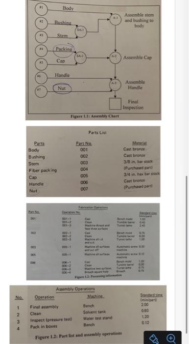
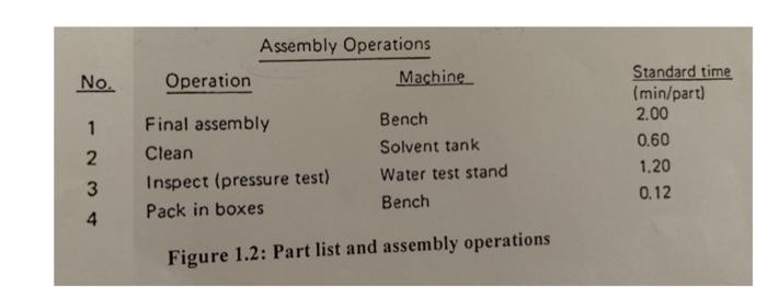
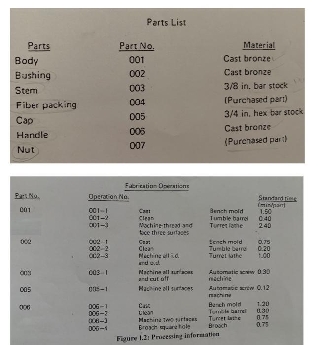
An assembly chart for a simple gate valve is given in figure 1.1, part list and assembly information for the gate valve and processing information are given in figure 1.2. The following information is also available:
a. Casting are manufactured in-house.
b. Bar stock, nuts, screws, packaging can be obtained from a local supplier.
c. The design engineer specified that body bushing and handle be made of cast bronze and the cap and stem of the valve be machined from standard brass bar stock.
d. The following need to be fabricated: the bushing, stem, cap, handle.
e. Inspection is required for all fabricated parts prior to delivery to final assembly. Construct an operation process chart, precedence diagram and rout sheets.
Step by Step Solution
There are 3 Steps involved in it
1 Expert Approved Answer
Step: 1 Unlock

Question Has Been Solved by an Expert!
Get step-by-step solutions from verified subject matter experts
Step: 2 Unlock
Step: 3 Unlock