

Question: Based on the state diagram provided below, design a digital circuit that accurately represents the open and closed states of a door, including the transitions
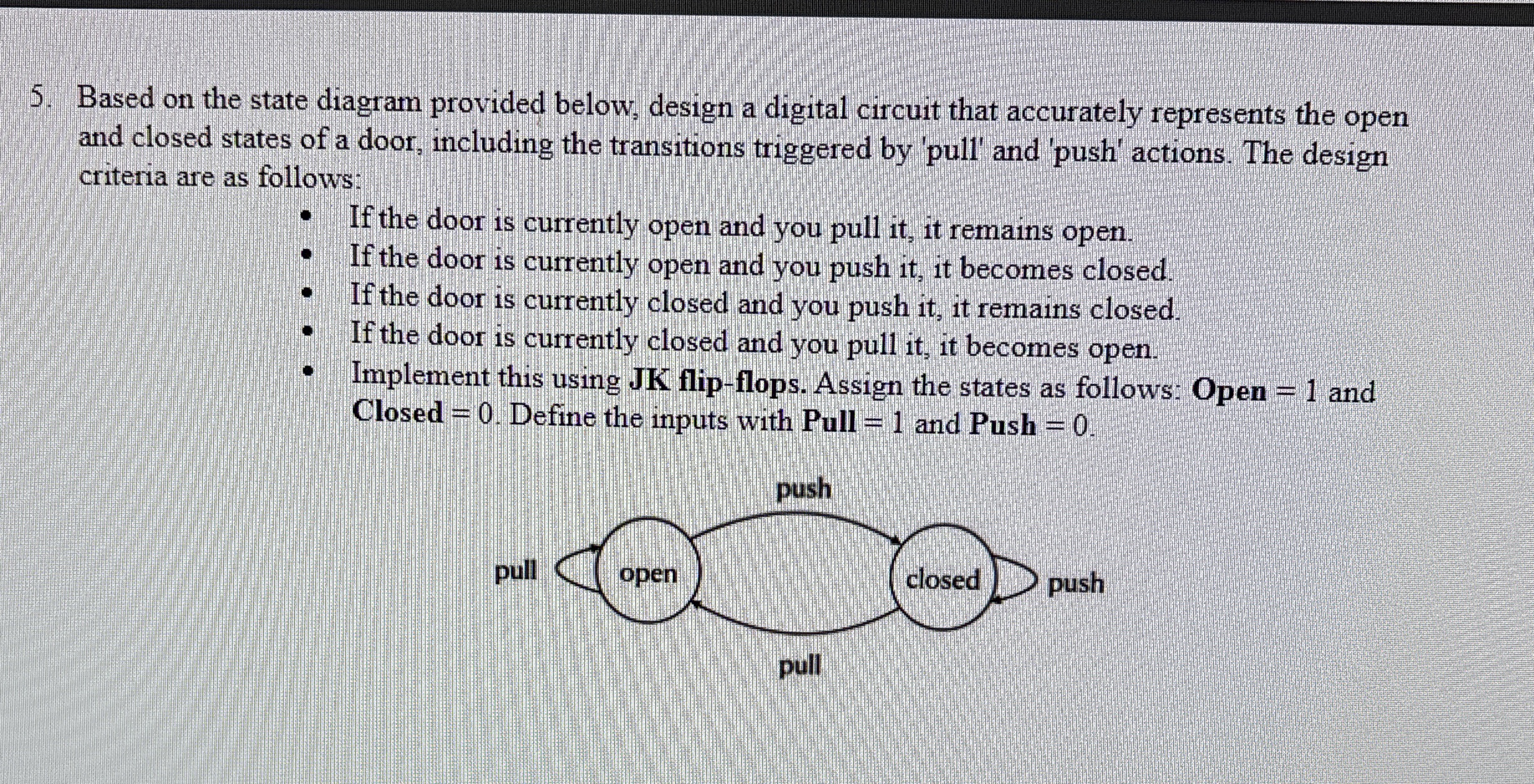
Based on the state diagram provided below, design a digital circuit that accurately represents the open and closed states of a door, including the transitions triggered by 'pull' and 'push' actions. The design criteria are as follows:
If the door is currently open and you pull it it remains open.
If the door is currently open and you push it it becomes closed.
If the door is currently closed and you push it it remains closed.
If the door is currently closed and you pull it it becomes open.
Implement this using JK flipflops. Assign the states as follows: Open and Closed Define the inputs with Pull and Push
Step by Step Solution
There are 3 Steps involved in it
1 Expert Approved Answer
Step: 1 Unlock

Question Has Been Solved by an Expert!
Get step-by-step solutions from verified subject matter experts
Step: 2 Unlock
Step: 3 Unlock