

Question: Branch M u Add Add u ALU operation Data PC Register # Registers Register # Address Instruction Instruction memory ALU MemWrite Address Zero Data memory
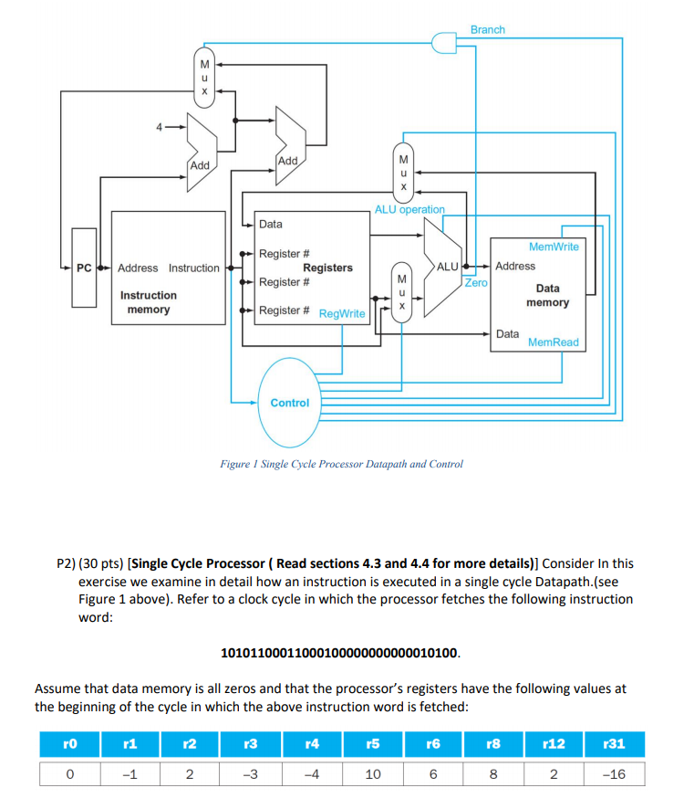
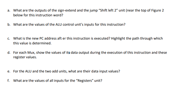
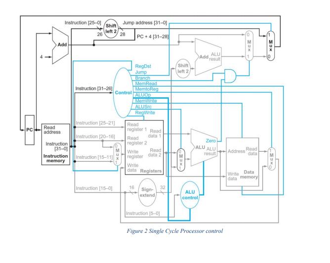
Branch M u Add Add u ALU operation Data PC Register # Registers Register # Address Instruction Instruction memory ALU MemWrite Address Zero Data memory Register # RegWrite Data MemRead Control Figure 1 Single Cycle Processor Datapath and Control P2) (30 pts) (Single Cycle Processor ( Read sections 4.3 and 4.4 for more details)] Consider In this exercise we examine in detail how an instruction is executed in a single cycle Datapath.(see Figure 1 above). Refer to a clock cycle in which the processor fetches the following instruction word: 10101100011000100000000000010100. Assume that data memory is all zeros and that the processor's registers have the following values at the beginning of the cycle in which the above instruction word is fetched: ro r1 r2 r4 r5 r6 18 r12 r31 0 -1 2. -3 -4 10 6 00 N -16 a. What are the outputs of the sign-extend and the jump Shift left 2" unit (near the top of Figure 2 below for this instruction word? b. What are the values of the ALU control unit's inputs for this instruction? C. What is the new PC address after this instruction is executed? Highlight the path through which this value is determined. d. For each Mux, show the values of its data output during the execution of this instruction and these register values. e. For the ALU and the two add units, what are their data input values? f. What are the values of all inputs for the "Registers" unit? Jump address (31-01 Instruction [25-01 Shift left 2 26 28 PC 4 [31-28) Add > Add ALU result 1 Shift left 2 RegDst Jump Branch MemRead Instruction (31-26) MemtoReg Control ALUOp Memwita ALUSTO RegWrite Instruction 25-21) Read PC Read address register 1 Read Instruction (20-16) Zero Read data 1 register 2 Write Read ALU ALU Instruction [31-01 Instruction memory - result Address Read data Instruction (15-111 register data 2 Write data Registers Write Data data memory Instruction (15-01 16 32 Sign- extend ALU control Instruction (5-0) Figure 2 Single Cycle Processor control
Step by Step Solution
There are 3 Steps involved in it

Get step-by-step solutions from verified subject matter experts