

Question: breadboard 4-Bit Binary Count In the first part of the lab we want to construct a 4 -bit binary counter. We will use this counter
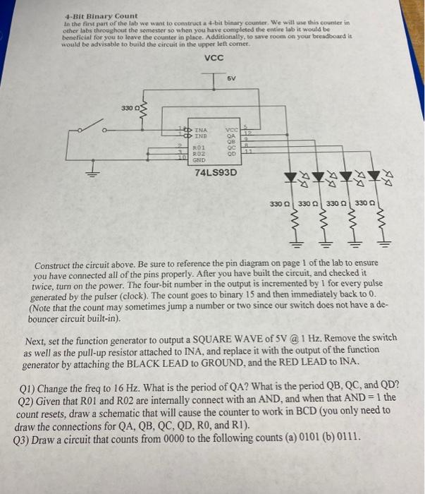
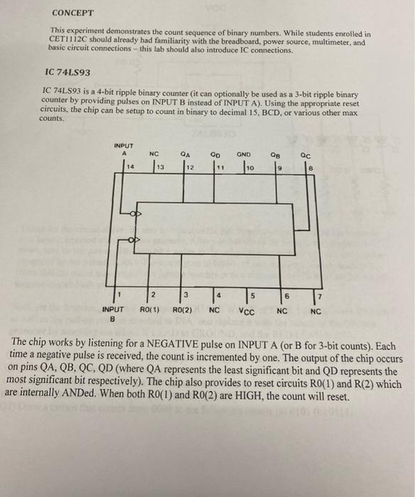
4-Bit Binary Count In the first part of the lab we want to construct a 4 -bit binary counter. We will use this counter in other labs throeghout the semester so when you have completed the entire lab it would be beneficial for you to leave the counter in place. Additionally, to save room on yeur bceadboard it. would be advisable to build the circuit in the upper left comer. Construct the circuit above. Be sure to reference the pin diagram on page 1 of the lab to ensure you have connected all of the pins properly. After you have built the circuit, and checked it twice, turn on the power. The four-bit number in the output is incremented by 1 for every pulse generated by the pulser (clock). The count goes to binary 15 and then immediately back to 0. (Note that the count may sometimes jump a number or two since our switch does not have a debouncer circuit built-in). Next, set the function generator to output a SQUARE WAVE of 5V @ 1 Hz. Remove the switch as well as the pull-up resistor attached to INA, and replace it with the output of the function generator by attaching the BLACK LEAD to GROUND, and the RED LEAD to INA. Q1) Change the freq to 16Hz. What is the period of QA ? What is the period QB,QC, and QD ? Q2) Given that R01 and R02 are internally connect with an AND, and when that AND=1 the count resets, draw a schematic that will cause the counter to work in BCD (you only need to draw the connections for QA,QB,QC,QD,R0, and R1 ). Q3) Draw a circuit that counts from 0000 to the following counts (a) 0101 (b) 0111. CONCEPT This experiment demonstrates the count sequence of binary numbers. While students enrolled in CET1112C should already had familiarity with the breadboard, power source, multimeter, and basic circuit connections - this lab should also introduce IC connections. IC 74L.S93 IC 74 LS 93 is a 4-bit ripple binary counter (it can optionally be used as a 3-bit ripple binary counter by providing pulses on INPUT B instead of INPUT A). Using the appropriate reset circuits, the chip can be setup to count in binary to decimal 15. BCD, or various other max counts. The chip works by listening for a NEGATIVE pulse on INPUT A (or B for 3-bit counts). Each time a negative pulse is received, the count is incremented by one. The output of the chip occurs on pins QA,QB,QC,QD (where QA represents the least significant bit and QD represents the most significant bit respectively). The chip also provides to reset circuits R0(1) and R(2) which are internally AND.d. When both R0(1) and R0(2) are HIGH, the count will reset
Step by Step Solution
There are 3 Steps involved in it

Get step-by-step solutions from verified subject matter experts