

Question: Consider the following diagram that represents a small data Path of 16-bit computer system: R8 (16-bits wide) RI (16-bits wide) RO (16-bits wide) 16-bits Div
Consider the following diagram that represents a small data Path of 16-bit computer system:
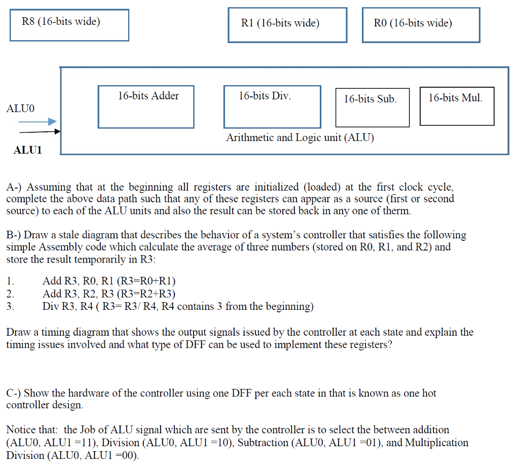
R8 (16-bits wide) RI (16-bits wide) RO (16-bits wide) 16-bits Div 16-bits Adder 16-bits Sub. 16-bits Mul. ALU0 Arithmetic and Logic unit (ALU) ALU1 A- Assuming that at the beginning all registers are initialized (loaded) at the first clock cycle, complete the above data path such that any of these registers can appear as a source (first or second source) to each of the ALU units and also the result can be stored back in any one of therm. B- Draw a stale diagram that describes the behavior of a system's controller that satisfies the following simple Assembly code which calculate the average of three numbers (stored on RO, RI, and R2) and store the result temporarily in R3 l. Add R3, RO, RI (R3 RO+R 1) 2. Add R3, R2, R3 (R3 R2+R3) 3. Div R3, R4 (R3 R3 R4, R4 contains 3 from the beginning Draw a timing diagram that shows the output signals issued by the controller at each state and explain the timing issues involved and what type of DFF can be used to implement these registers? C- Show the hardware of the controller using one DFF per each state in that is known as one hot controller design. Notice that: the Job of ALU signal which are sent by the controller is to select the between addition CALU0, ALUl 1 l), Division (ALU0, ALU1 100, Subtraction (ALU0, ALU1 01), and Multiplication Division (ALU0, ALUI -00)
Step by Step Solution
There are 3 Steps involved in it

Get step-by-step solutions from verified subject matter experts