

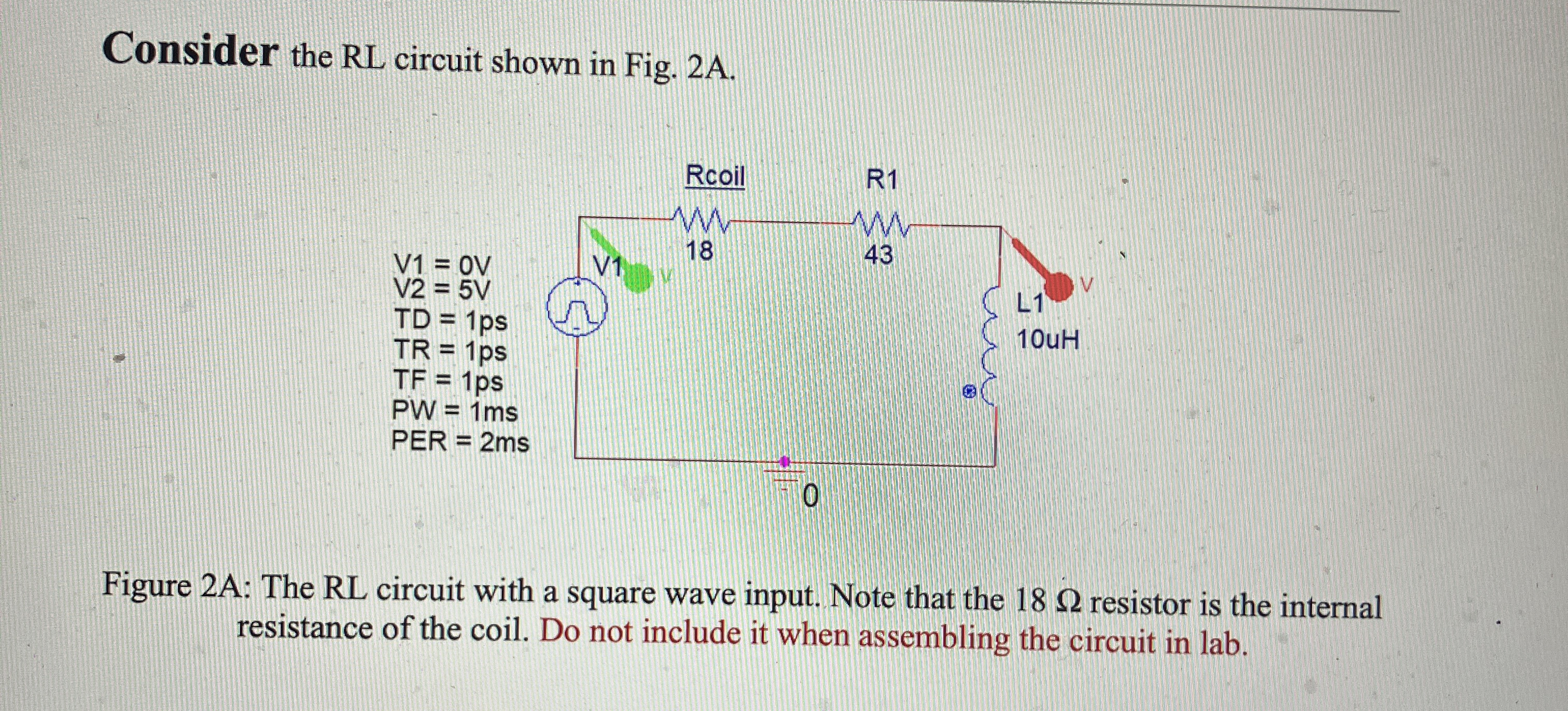
Question: Consider the RL circuit shown in Fig. 2 A . Figure 2 A: The RL circuit with a square wave input. Note that the 1
Consider the RL circuit shown in Fig. A
Figure A: The RL circuit with a square wave input. Note that the resistor is the internal resistance of the coil. Do not include it when assembling the circuit in lab. Set the resistor initially to ohms in series with an ohm resistor and the inductor to uH Analyze the circuit in time domain and find the governing equation. Your analysis should be for one complete cycle of square wavepulse with a frequency of Hz and amplitude going from V to V for ms and is then for another ms Show your mesh or node equations and how you arrive at your governing equation. SHOW ALL MATHEMATICAL STEPS
Step by Step Solution
There are 3 Steps involved in it
1 Expert Approved Answer
Step: 1 Unlock

Question Has Been Solved by an Expert!
Get step-by-step solutions from verified subject matter experts
Step: 2 Unlock
Step: 3 Unlock