

Question: Create the following block diagram using Simscape. Run it to generate a plot in MATLAB format. Add a title, x-label and y-label to your graph.
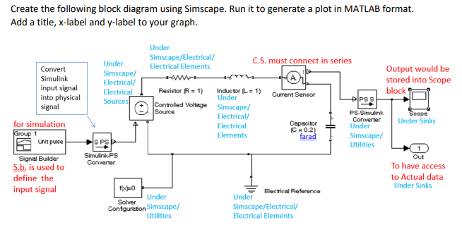
Create the following block diagram using Simscape. Run it to generate a plot in MATLAB format. Add a title, x-label and y-label to your graph. PSS Convert Simulink input signal into physical signal for simulation Group 1 Unit pulse Under Simscape/Electrical/ Under C.S. must connect in series Electrical Elements Output would be Simscape/ M Electrical/ stored into Scope Electrical Resistor R = 1) Inductor L = 1) block Under Current Sensor Sources Controled Voltage Simscape/ Source Electrical/ PS Simulink Scope Converter Electrical Capacitor Under Sinks Under C-02) Elements farad Simscape/ HS PS Utilities Simulink.PS Out Converter To have access to Actual data Under Sinks fy Electrical Reference Under Under Solver Confguration Simscape/ Simscape/Electrical/ Utilities Electrical Elements Signal Builder S.b, is used to define the input signal Ako Create the following block diagram using Simscape. Run it to generate a plot in MATLAB format. Add a title, x-label and y-label to your graph. PSS Convert Simulink input signal into physical signal for simulation Group 1 Unit pulse Under Simscape/Electrical/ Under C.S. must connect in series Electrical Elements Output would be Simscape/ M Electrical/ stored into Scope Electrical Resistor R = 1) Inductor L = 1) block Under Current Sensor Sources Controled Voltage Simscape/ Source Electrical/ PS Simulink Scope Converter Electrical Capacitor Under Sinks Under C-02) Elements farad Simscape/ HS PS Utilities Simulink.PS Out Converter To have access to Actual data Under Sinks fy Electrical Reference Under Under Solver Confguration Simscape/ Simscape/Electrical/ Utilities Electrical Elements Signal Builder S.b, is used to define the input signal Ako
Step by Step Solution
There are 3 Steps involved in it

Get step-by-step solutions from verified subject matter experts