

Question: Design a 4 - bit shift register that can ( 1 ) shift its information at right, ( 2 ) shift its information at left
Design a bit shift register that can shift its information at right, shift its information at left and asynchronously initialize to state when RST
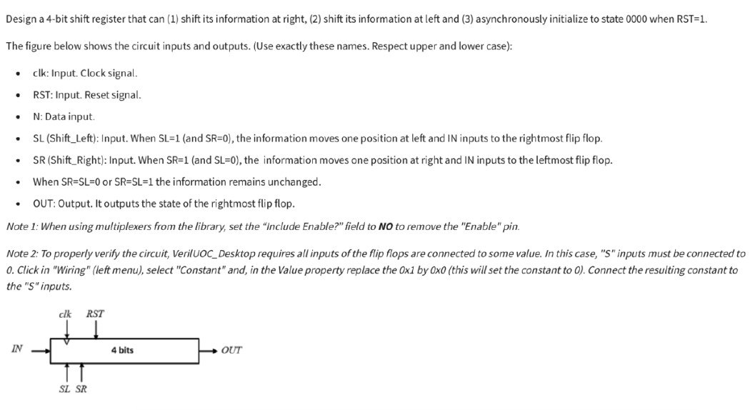
The figure below shows the circuit inputs and outputs. Use exactly these names. Respect upper and lower case:
clk: Input. Clock signal.
RST: Input. Reset signal.
N: Data input.
SL ShiftLeft: Input. When SLand SR the information moves one position at left and IN inputs to the rightmost flip flop.
ShiftRight: Input. When SRand SL the information moves one position at right and IN inputs to the leftmost flip flop.
When or the information remains unchanged.
OUT: Output. It outputs the state of the rightmost flip flop.
Note : When using multiplexers from the library, set the "Include Enable?" field to No to remove the "Enable" pin.
Note : To properly verify the circuit, VerilUOCDesktop requires all inputs of the flip flops are connected to some value. In this case, S inputs must be connected to
Click in "Wiring" left menu select "Constant" and, in the Value property replace the Ox by xthis will set the constant to Connect the resulting constant to
the S inputs.
Step by Step Solution
There are 3 Steps involved in it
1 Expert Approved Answer
Step: 1 Unlock

Question Has Been Solved by an Expert!
Get step-by-step solutions from verified subject matter experts
Step: 2 Unlock
Step: 3 Unlock