

Question: Design a 4-bit ALU that implements the following function table with 3-bit function select code, f_2f_1f_0. where OPA = x_3x_2x_1x_0 and OPB = y_3y_2y_1y_0 are
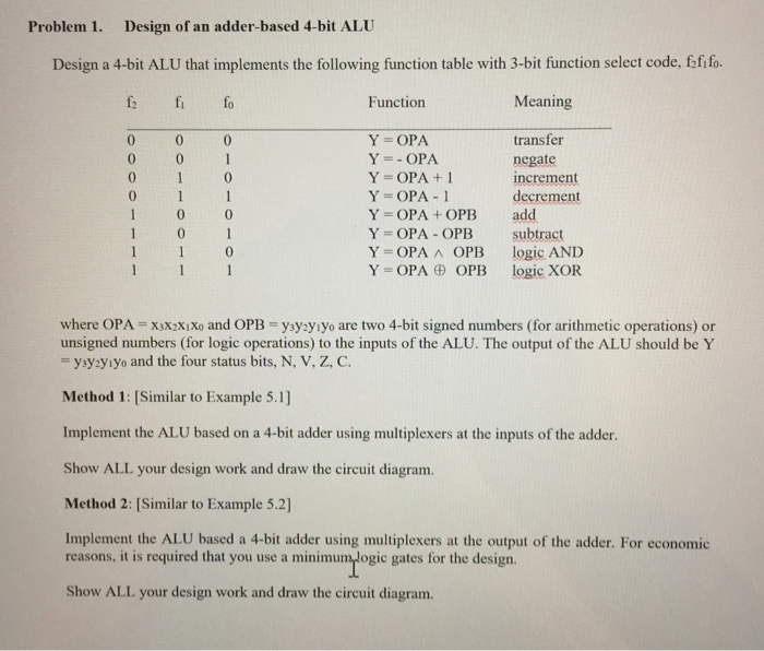
Design a 4-bit ALU that implements the following function table with 3-bit function select code, f_2f_1f_0. where OPA = x_3x_2x_1x_0 and OPB = y_3y_2y_1y_0 are two 4-bit signed numbers (for arithmetic operations) or unsigned numbers (for logic operations) to the inputs of the ALU. The output of the ALU should be Y = y_3y_2y_1y_0 and the four status bits, N, V, Z, C. Method 1: (Similar to Example 5.1] Implement the ALU based on a 4-bit adder using multiplexers at the inputs of the adder. Show ALL your design work and draw the circuit diagram. Method 2: [Similar to Example 5.2] Implement the ALU based a 4-bit adder using multiplexers at the output of the adder. For economic reasons, it is required that you use a minimum logic gates for the design. Show ALL your design work and draw the circuit diagram. Design a 4-bit ALU that implements the following function table with 3-bit function select code, f_2f_1f_0. where OPA = x_3x_2x_1x_0 and OPB = y_3y_2y_1y_0 are two 4-bit signed numbers (for arithmetic operations) or unsigned numbers (for logic operations) to the inputs of the ALU. The output of the ALU should be Y = y_3y_2y_1y_0 and the four status bits, N, V, Z, C. Method 1: (Similar to Example 5.1] Implement the ALU based on a 4-bit adder using multiplexers at the inputs of the adder. Show ALL your design work and draw the circuit diagram. Method 2: [Similar to Example 5.2] Implement the ALU based a 4-bit adder using multiplexers at the output of the adder. For economic reasons, it is required that you use a minimum logic gates for the design. Show ALL your design work and draw the circuit diagram
Step by Step Solution
There are 3 Steps involved in it

Get step-by-step solutions from verified subject matter experts