

Question: Design a custom BCD-to-7-segment decoder circuit as pictured below that will have the following 1. features: The output will be connected to a common-anode 7-segment
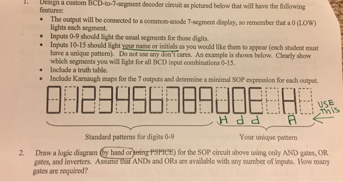
Design a custom BCD-to-7-segment decoder circuit as pictured below that will have the following 1. features: The output will be connected to a common-anode 7-segment display, so remember that a 0 (LOW) lights each segment Inputs 0-9 should light the usual segments for those digits. . Inputs 10-15 should light your name or initials as you would like them to appear (each student must which segments you will light for all BCD input combinations 0-15. Include a truth table. Include Karnaugh maps for the 7 outputs and determine a minimal SOP expression for each output . USE Standard patterns for digits 0-9 Your unique pattern 2. Draw a logic diagram by hand orusing PSPIeE) for the SOP circuit above using only AND gates, OR gates, and inverters. Assume that ANDs and ORs are available with any number of inputs. How many gates are required
Step by Step Solution
There are 3 Steps involved in it

Get step-by-step solutions from verified subject matter experts