

Question: Design of Asynchronous State Machine Design Steps: 1. Prmitive State Diagram. 2. Primitive Flow Table. 3. Redution of Primitive flow Table. 4. Merging. 5. Merger
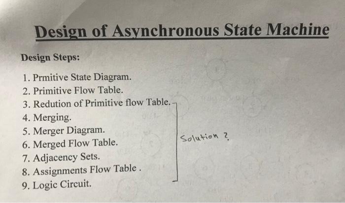
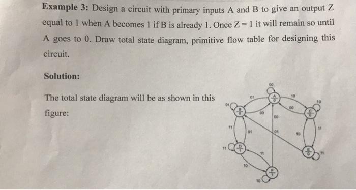
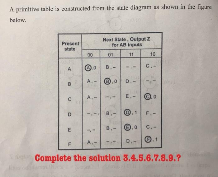
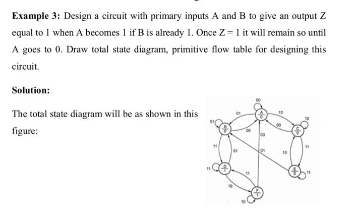
Design of Asynchronous State Machine Design Steps: 1. Prmitive State Diagram. 2. Primitive Flow Table. 3. Redution of Primitive flow Table. 4. Merging. 5. Merger Diagram. 6. Merged Flow Table. 7. Adjacency Sets. 8. Assignments Flow Table. 9. Logic Circuit Solution ? Example 3: Design a circuit with primary inputs A and B to give an output Z equal to 1 when A becomes 1 if B is already 1. Once Z = 1 it will remain so until A goes to 0. Draw total state diagram, primitive flow table for designing this circuit. Solution: 10 The total state diagram will be as shown in this figure: 00 11 11 Or 01 10 11 17 O 19 A primitive table is constructed from the state diagram as shown in the figure below. Present state Next State , Output Z for AB inputs 01 11 10 00 B.- C.- A A.- .0 B D.- A.- E- 0 - D B.- F.- B.- 0.0 E C.- F A.- D.- Complete the solution 3.4.5.6.7.8.9.? Example 3: Design a circuit with primary inputs A and B to give an output Z equal to 1 when A becomes 1 if B is already 1. Once Z= 1 it will remain so until A goes to 0. Draw total state diagram, primitive flow table for designing this circuit. Solution: 10 The total state diagram will be as shown in this figure: 00 00 100 11 01 01 10 11 10 Design of Asynchronous State Machine Design Steps: 1. Prmitive State Diagram. 2. Primitive Flow Table. 3. Redution of Primitive flow Table. 4. Merging. 5. Merger Diagram. 6. Merged Flow Table. 7. Adjacency Sets. 8. Assignments Flow Table. 9. Logic Circuit Solution ? Example 3: Design a circuit with primary inputs A and B to give an output Z equal to 1 when A becomes 1 if B is already 1. Once Z = 1 it will remain so until A goes to 0. Draw total state diagram, primitive flow table for designing this circuit. Solution: 10 The total state diagram will be as shown in this figure: 00 11 11 Or 01 10 11 17 O 19 A primitive table is constructed from the state diagram as shown in the figure below. Present state Next State , Output Z for AB inputs 01 11 10 00 B.- C.- A A.- .0 B D.- A.- E- 0 - D B.- F.- B.- 0.0 E C.- F A.- D.- Complete the solution 3.4.5.6.7.8.9.? Example 3: Design a circuit with primary inputs A and B to give an output Z equal to 1 when A becomes 1 if B is already 1. Once Z= 1 it will remain so until A goes to 0. Draw total state diagram, primitive flow table for designing this circuit. Solution: 10 The total state diagram will be as shown in this figure: 00 00 100 11 01 01 10 11 10
Step by Step Solution
There are 3 Steps involved in it

Get step-by-step solutions from verified subject matter experts