

Question: Design of logic circuits using universal gates. Pre-Lab: The block diagram shown below represents a voting booth monitoring system. For privacy reasons, a voting booth
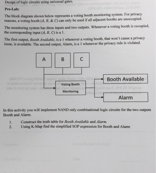
Design of logic circuits using universal gates. Pre-Lab: The block diagram shown below represents a voting booth monitoring system. For privacy reasons, a voting booth (A, B, & C) can only be used if all adjacent booths are unoccupied. The monitoring system has three inputs and two outputs. Whenever a voting booth is occupied, the corresponding input (A, B, C) is a 1. The first output, Booth Available, is a 1 whenever a voting booth, that won't cause a privacy issue, is available. The second output, Alarm, is a 1 whenever the privacy rule is violated. Booth Available Voting Booth Monitoring Alarm In this activity you will implement NAND only combinational logic circuits for the two outputs Booth and Alarm. 1. Construct the truth table for Booth Available and Alarm. 2. Using K-Map find the simplified SOP expression for Booth and Alarm
Step by Step Solution
There are 3 Steps involved in it

Get step-by-step solutions from verified subject matter experts